Installation of pistons and connecting rods VR6
♦ Arrange the connecting rods according to the cylinder numbers. The bosses on the connecting rods and bearing caps must be on the drive chain side (see Fig. 163).
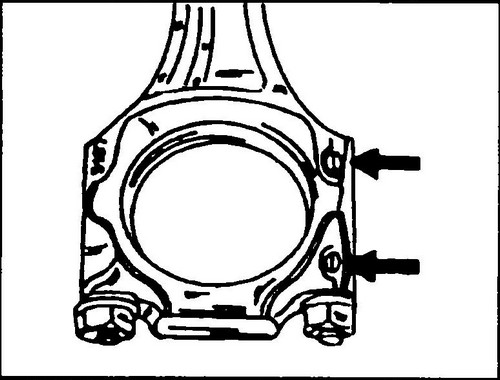
Rice. 163 Lugs on connecting rods and caps must be opposite each other and directed towards the belt pulley
The arrows on the bottoms of the pistons must be directed as shown in fig.
161. ♦ The differences are described below.
♦ After connecting the connecting rod to the crankshaft, tap the connecting rod cover lightly.
Ensure that both labels match according to Fig. 163 so as not to make a mistake at the last moment. Lubricate the threaded surfaces of the connecting rod bolts with engine oil, screw in both bolts. Tighten the bolts in stages, tightening torque 30 Nm, and from this position, tighten the bolts a further 90º, i.e. ¼ turn. ♦ After installing the connecting rod, rotate the crankshaft several times to check for correct assembly.
♦ Recheck the labeling of all parts and correct assembly.
♦ Re-measure the axial clearance between the bearing surface of the connecting rod and the surface of the crankshaft journal.
The gap should not exceed 0.31 mm. ♦ Install the oil sump on the Volkswagen Transporter T4 .
Perform all further work in the reverse order to disassembly.

Rice. 164 Removing the piston pin

Rice.
165 Connecting rod and piston group 1 - piston rings, 2 - piston, 3 - connecting rod, 4 - bearing cap, 5 - bolts, 6 - bearing shells, 7 - cylinder block, 8 - piston pin, 9 - retaining ring