Bosch's Motronic fuel injection system is installed
on the VR6 Volkswagen Transporter T4 Motronic is an electronic engine management system that injects fuel into the intake manifold at regular intervals and combines control of the fuel injection (injector) and ignition systems according to engine load, desired operating mode and taking into account a number of other factors, i.e. . the supplied fuel and ignition timing are determined based on data received from a plurality of sensors. This means that the microprocessor module sends signals to the injectors and the ignition coil to change the advance angle, thus ensuring an optimal match between the injection point and the moment the spark appears. The system collects and processes data on the engine temperature at the moment, the speed and position of the crankshaft, the amount of air supplied, the position of the throttle valve, etc. (see Fig. 305 and 306). The Motronic injection system provides the engine with the optimal composition and quantity of the fuel-air mixture in any operating mode.
The necessary conditions for checking the frequency XX and the CO content are: the engine must be warmed up to operating temperature (engine oil at least 80ºС).
- all consumers of electric current must be turned off.
- if an air conditioner is installed, it must be turned off.
- the exhaust system must be sealed.
CO content can be measured using a conventional gas analyzer.
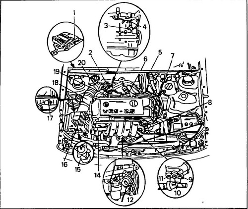
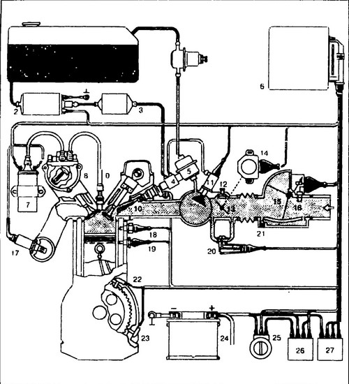
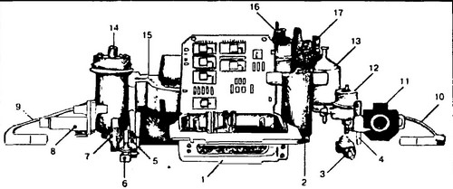
The outlet hose for connecting the gas analyzer is located next to the throttle body. The CO content should be 0.3-1.2%, it cannot be adjusted manually. See fig. 1 for location of units and system sensors. 298, the circuit diagram is shown in fig. 299, the appearance of the units is shown in fig. 300.
Rice.
298 Approximate location of the Motronic system units in the engine compartment 1 - microprocessor module, 2 - throttle body, 3 - ignition timing sensor 1 (G61), 4 - exhaust gas hose for checking CO content, 5 - ignition coil (No. 152), 6 - frequency stabilization valve XX (No. 71), 7 - ignition distributor with Hall sensor (G40), 8 - fuel pressure regulator, 9 - temperature sensor, for air conditioning (black), 10 - coolant temperature sensor (blue) (G62 ), Motronic systems (two-pin), 11 - temperature sensor (yellow) (G2 / F87), (four-pin), 12 - speed / crankshaft position sensor (G28), 13 - ignition timing sensor 2 (G66), 14 - nozzle (No. 30-33, No. 83, No. 84), 15 - activated carbon tank, located under the air filter, 16 - air filter, 17 - activated carbon tank solenoid valve (No. 80), 18 - air flow meter ( G70), 19 - throttle position sensor (potentiometer) (G89), 20 - intake duct
Rice.
299 Schematic diagram of the Motronic fuel injection system 1 - fuel tank, 2 - electric fuel pump, 3 - fuel filter, 4 - injector manifold, 5 - fuel pressure regulator, 6 - microprocessor module, 7 - ignition coil, 8 - ignition device , 9 - spark plug, 10 - injector, 11 - starting injector, 12 - idle speed adjusting screw, 13 - damper. 14 - damper position sensor, 15 - fuel flow meter, 16 - air temperature sensor, 17 - lambda probe, 18 - temperature-time sensor, 19 - engine temperature sensor, 20 - additional air supply valve, 21 - mixture adjustment screw, 22 - crankshaft position sensor, 23 - speed sensor, 24 - battery, 25 - ignition switch, 26 - main relay, 27 - fuel pump relay
Rice.
300 The main components of the system 1 - microprocessor module, 2 - idle speed controller, 3 - injector, 4 - starting injector, 5 - temperature-time sensor, 6 - engine temperature sensor, 7 - probe, 8 - auxiliary air valve, 9 - crankshaft position sensor, 10 - speed sensor, 11 - throttle position sensor, 12 - fuel pressure regulator, 13 - fuel filter, 14 - ignition coil, 15 - fuel flow meter, 16 - ignition device, 17 - electric fuel pump.


