Auxiliary air valve
The valve (see Fig. 276) supplies the required amount of air during the start of a cold engine of the vehicle Transporter T4 . This valve performs exactly the same function as the automatic starting device ("choke") in carbureted engines.
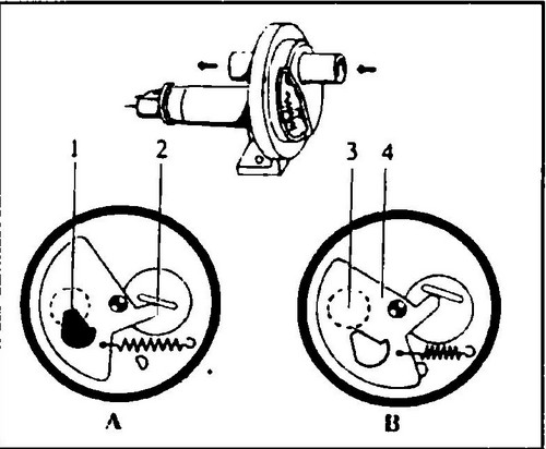
Rice.
276 Additional air supply valve with electric heating 1 - connector, 2 - heating winding, 3 - thermobimetallic element, A - damper with a hole
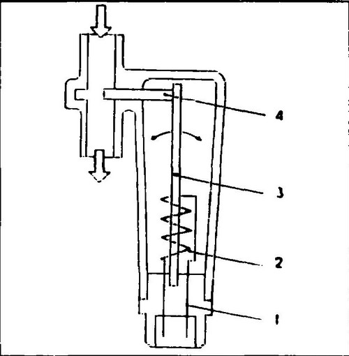
The cross section of the channel (3) (see Fig. 277) is regulated by a damper (4) in which there is a groove (1) for the passage of air. The change in damper position is the result of the action of a thermobimetal element with a heating winding (2) permanently energized by means of a double remote switch.
Rice. 277 Additional air supply valve
When the temperature rises, the thermobimetallic element, overcoming the resistance of the spring, moves the damper, reducing the supply of additional air, until the engine is completely warmed up, at which the air supply to the manifold in this way will be completely closed.
Possible malfunctions caused by improper operation of the additional air valve
- The engine does not start or starts with difficulty.
- The engine stalls immediately after starting it.
- Rough idle.
Control relays (see fig. 278)
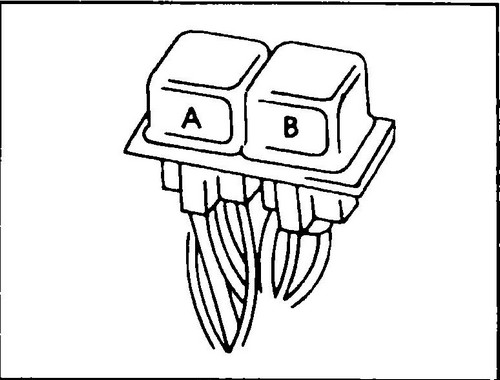
Rice. 278 Relay box
A - fuel pump relay
The relay causes the fuel pump to turn on (connection of the pump system to ground) after receiving a signal from the microprocessor module, which is the result of a change in the crankshaft speed.
B - main relay
The relay turns on the power supply of the microprocessor module and injectors after receiving a signal from the ignition switch.
Checking the idle speed and the CO content in the exhaust gases
To control the frequency of XX and the CO content in the exhaust gases, a special device is used.
If you are going to perform these operations yourself, you will have to use a tachometer and a gas analyzer. Connect both devices according to their manufacturer's instructions. Before starting work, the following conditions must be ensured:
The engine must be warmed up to operating temperature.
All electrical consumers must be turned off.
If the car has an air conditioning system, it must be turned off.
Ignition adjustment should be correct.
The exhaust system must be sealed.
The lambda probe must be working.
The frequency stabilization system XX must be operational.
♦ Connect the tachometer according to the manufacturer's instructions.
♦ Connect the gas analyzer according to the manufacturer's instructions.
♦ Determine the XX frequency and the CO content of the exhaust gases.
The frequency XX of the 2.0 engine must be 880 ± 50 rpm.
The content of CO in the exhaust gases should be: with a lambda probe 0.7 ± 0.2% and 1.0 ± 0.5% without it. If the above values are not met, check the tightness of the vacuum hoses.
If the values obtained are not correct, the XX frequency should be adjusted.
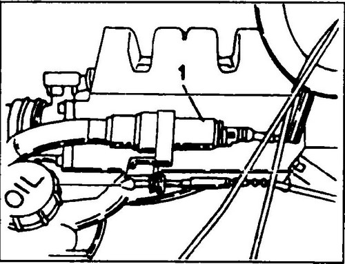
But for this you need to have some experience with fuel injection systems. ♦ Remove the crankcase ventilation hose (1 Fig. 279) from the pressure regulator (2) and turn the end of the hose so that only clean air enters.
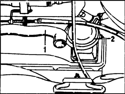
Rice. 279 Crankcase ventilation hose (1) disconnected from the pressure regulator (2)
♦ Let the engine run at frequency XX with the choke closed until the radiator fan turns on, then disconnect the connector shown by the arrow in fig. 280. Press the gas pedal three times to cause the engine to briefly increase the speed to 3000 rpm, and then return to the frequency XX.
Rice. 280 Coolant temperature sensor connector (see arrow)
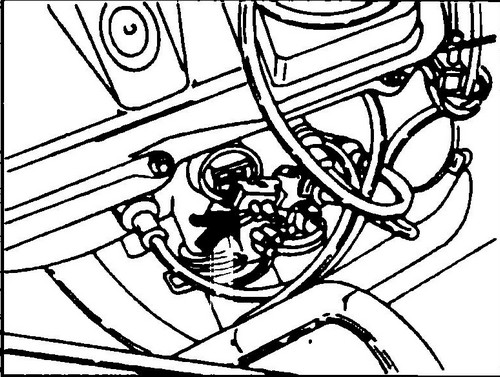
♦ To adjust the XX frequency, use the screw (B, fig. 281), and the CO content in the exhaust gases - the screw (A). The screw hole (A) is closed with a special cap. By turning the adjusting screws alternately, set the desired frequency XX and the CO content in the exhaust gases.
Rice. 281 Location of CO content adjustment screw (A) and XX frequency adjustment screw (B)
♦ Replace the temperature sensor connector.
♦ Install a new protective cap on the bushing that covers the screw (A).
Check of system of stabilization of frequency of idling
At first it is necessary to check up, whether the stabilization system works, and then whether it stabilizes idling.
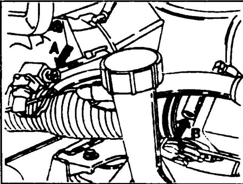
♦ Switch on the ignition. Frequency stabilization valve XX (1, fig. 282) should work. If not, remove the connector from the valve terminals (1) and measure the resistance between the valve terminals. It should be 2.0 -10.0 ohms. If the measurement is within the specified range, replace the valve connector. If not, replace the valve.
Rice. 282 Valve frequency stabilization XX (I)
In order to check if the idle speed stabilizes, you will need an ammeter (with a large reading range).
The engine must be warm, the XX frequency must be correct, and the air supply system must be completely sealed. Take measurements with the engine running. ♦ Remove the electrical wire from the connector on the end of the valve and connect an ammeter as shown in fig.
284. ♦ Start the engine and let it idle.
♦ After about a minute, briefly increase the frequency to 3000 rpm three times and read the ammeter reading, it should read 420 ±30 mA.
♦ Disconnect the coolant temperature sensor connector (fig. 280) and read the ammeter again.
The reading should correspond to the above value, but the pointer of the device should not fluctuate. ♦ Connect an ammeter to the electrical circuit of the stabilization valve.
If you failed to obtain the required values, most likely the reason for this is a malfunction of the microprocessor module and you will have to seek help from a VW service station.
The following are reasons that can cause significant deviations: - a cold engine,
- the air conditioning system is on,
- electrical consumers are on,
- the power steering gear is in the extreme position,
- the XX frequency is poorly adjusted,
- the ignition timing is incorrectly set.
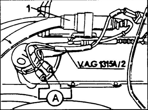
Rice. 283 Frequency stabilization check XX
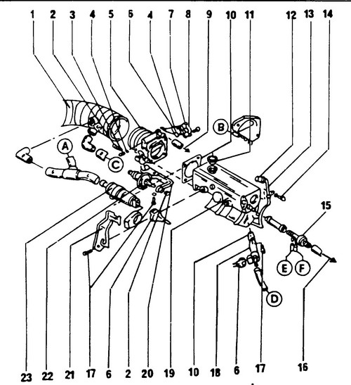
Rice.
284 Location of injection system components Letters show connections to other injection system diagrams (see fig. 285, 286 ) damper body, 6 - connector, 7 - damper position sensor, 8 - locking plate, 9 - to the activated carbon filter valve, 10 - gasket (disposable), 12 - plug, 13 - pipe for measuring the CO content in exhaust gases, 14 - bolt, 15 Nm, 15 - check valve, 16 - to the vacuum brake booster, 17 - bolt, 10 Nm, 18 - starting nozzle, 19 - intake manifold, 20 - vacuum booster bracket, 21 - damper rod shell bracket, 22 - vacuum booster (car with automatic transmission), 23 - frequency stabilization valve XX
All further work can only be done with the help of special tools, so you need to contact a VW service station.
Replacing the fuel tank T4 . Digifant injection system .