Checking injection system components
To check individual sensors, drawings showing the position of the nodes and parts of the system will be useful. To access individual elements of the system, fold down the front panel of the Transporter T4 .
The air filter has an adjustment of the amount of incoming warm and cold air.
The lambda probe connector is located at the engine support on the right side. The plug (11) is located on the pipe for measuring the CO content in the exhaust gases.
The vacuum hose (12) is connected to the intake manifold check valve and the intake manifold pressure sensor located in the microprocessor module.
The microprocessor module of the Digifant system (13) is fixed in the engine compartment on the left side.
The ignition coil (14) is attached to the left side of the engine compartment.
The coolant temperature sensor provides a coolant temperature signal to the microprocessor module.
The potentiometer for adjusting the CO content in the exhaust gases (21) is equipped with a screw for adjusting the CO content and the intake air temperature sensor.
Connector (A) (fig. 284) is connected to connector (A) (fig. 287).
Connector (B) (fig. 284) is connected to connector (B) (fig. 287).
Connectors (C), (D) and (E) (fig. 284) are connected to the corresponding connectors in fig. 285.
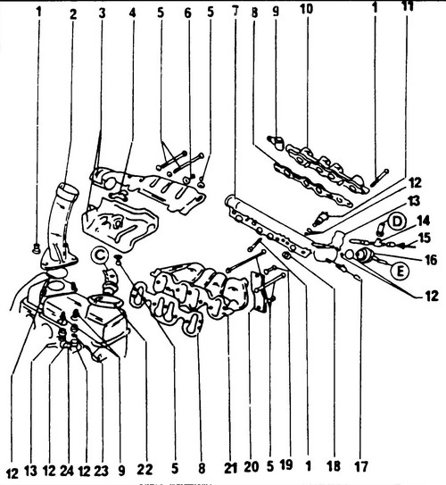
Rice.
285 Components of the injection system Fuel lines and connectors marked with letters are connected to the corresponding elements in fig.
284, 286 1 - bolt, 10 Nm, 2 - oil filler neck, 3 - warm air guide, 4 - retainer, 5 - bolt, 25 Nm, 6 - nut, 40 Nm, 7 - fuel manifold (lower part), 8 - gasket , 9 - connector, 10 - fuel manifold (top), 11 - injector, 12 - o-ring, 13 - spring clip, 14 - tee, 15 - black fuel line, 16 - fuel pressure regulator 17 - blue fuel line, 18 - o-ring ring, 19 - bolt, 40 Nm, 20 - intake and exhaust manifold strip, 21 - intake manifold, 22 - pressure control valve in the crankcase ventilation system, 23 - coolant temperature sensor, 24 - fan thermal switch
Connector (F) (fig. 284) is connected to connector (F) (fig. 286).

Rice.
Digifan injection system electronic module 1 - ground bus, 2 - connector, 3 - Digifant injection system microprocessor module, 4 - lambda probe connector, 5 - probe
Rice.
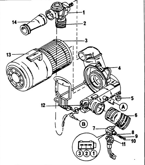
287 Air filter device 1 - valve body for adjusting the temperature of the incoming air, 2 - warm air pipe, 3 - filter element, 4 - air filter housing, 5 - rubber washer, 6 - intake air duct, 7 - potentiometer for adjusting the CO content in the exhaust gases , 8 - O-ring, 9 - screw for adjusting the CO content in the exhaust gases, 10 - plug, 11 - connector, 12 - temperature regulator, 13 - air filter housing, 14 - air inlet pipe
Correctly connect an inlet air line (1) (fig. 284).
Replace the O-ring at every disassembly.
The damper position sensor is connected to the microprocessor module with a three-pin connector.
With automatic transmission, the four-pin connector is used to connect to the microprocessor module of the automatic transmission control unit. The o-ring (11, fig. 284) must be replaced at every disassembly.
Plug (12) must be hermetically sealed.
The check valve must be installed in the appropriate position.
Vacuum device (22) is installed only in vehicles with manual transmission.
The fuel manifold (7, fig. 285) can only be removed together with the injectors.
Replace rings (12) and (18) if they show signs of wear.
The fuel lines have different colors.
Wire (F) is connected to connector (F) in fig.
284 A support bar (20) is installed between the intake and exhaust manifolds.
On fig.
287 shows an electronic microprocessor module. The connector (2) can only be disconnected when the ignition is switched off. In this case, it is necessary to move the retaining spring and remove the connector in the direction indicated in fig. 286. The microprocessor module controls fuel injection, ignition timing, XX frequency stabilization, and mixture quality control using a lambda probe. The module is installed in the engine compartment on the left side. The supply voltage of the lambda probe can be measured between terminals (1) (red/black wire) and connector (2) (brown wire) of the probe socket (5). Before installation, the probe thread must be coated with G5.
This agent must not get into the opening of the probe body. On fig. 287 shows the system for cleaning the air entering the injection system. Connectors (A) and (B) must be connected to the corresponding elements in fig.
284. The inlet air duct (1) (fig. 284) has an air valve (2) (see fig. 287), which controls the temperature, is connected to the exhaust manifold support bar (see fig. 285).
When connecting the inlet pipe (6) (Fig. 287), pay attention to the tightness of its seal.
The temperature regulator must be installed correctly, the brass air fitting must point upwards.
Volkswagen T4 injector replacement . What is the Lambda T4 Transporter.