Block head repair
Valve springs
To check the mechanical characteristics of the valve springs, a special tool is required.
In the absence of a device, proceed as follows. ♦ Compare the spring removed from the engine with the new one.
To do this, install them in series on a long bolt through washers. With a nut, compress the new spring by 10-15 mm and measure the height of the old one. If the height difference is more than 7%, replace all old springs. ♦ Install the springs on a smooth surface with narrower coils downwards.
Attach a steel square to the springs and measure the amount of curvature of the spring along the side surface. The deviation must not exceed 2.0 mm. Otherwise, the spring is considered to be out of order. Valve guides
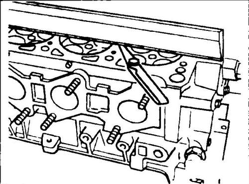
♦ Attach an indicator to the cylinder head (see fig. 77). Pull the valve up so that the end of the rod is aligned with the end of the guide. Place the indicator rod against the valve head and rock the valve in the guide while reading the indicator. If the value obtained is greater than 1.0 mm for the inlet and 1.3 mm for the exhaust valve, then you will need to replace the valve or its guide. Repeat the measurements with new valves, if the play is now more than normal, then the guides need to be replaced.
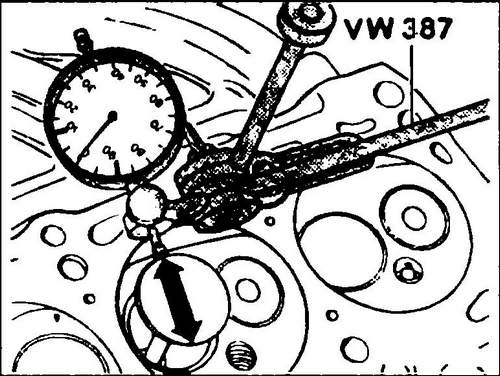
Rice. 77 Check valve stem clearance in guide
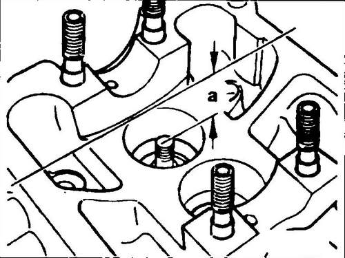
♦ Before replacing guides, check the general condition of the cylinder head. A block head with small cracks between the valve seats or between the valve seat and the threaded hole of the spark plug can be further used after appropriate processing. In this case, the crack width should not exceed 0.5 mm. After trimming the seating surface, the dimension "a" (see Fig. 78) must be at least 132.6 mm.
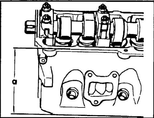
Rice. 78 Head height measurement
♦ To replace, knock out the old guide on the combustion chamber side using a stepped bar.
To facilitate the work, you can warm up the cylinder head. ♦ If it becomes necessary to replace the guides, the valves must also be replaced.
♦ Thoroughly lubricate the new guides with engine oil and press them into the cylinder head from the camshaft side.
Do not heat the block head before installing. ♦ After installation, ream the rail holes with special reamer No. 10-215.
If you do not have such a sweep, you can use an adjustable sweep. ♦ Open the guide holes for the exhaust and intake valves by the same size of 8.0 mm.
After replacing the guides, it is also necessary to mill the valve seats. Valve Seats
♦ Check the condition of the valve seats for wear, cracks or pitting. Small traces of wear can be removed with a 45º cone cutter. If the working chamfer of the seats is worn significantly more, then the seats must be re-machined. The angles and dimensions to be obtained as a result of processing are shown in Fig. 79 and 80 and in table No. 1. It is necessary to save the required parameters of the valve seats.
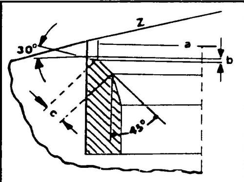
Rice.
79 Inlet valve seat dimensions
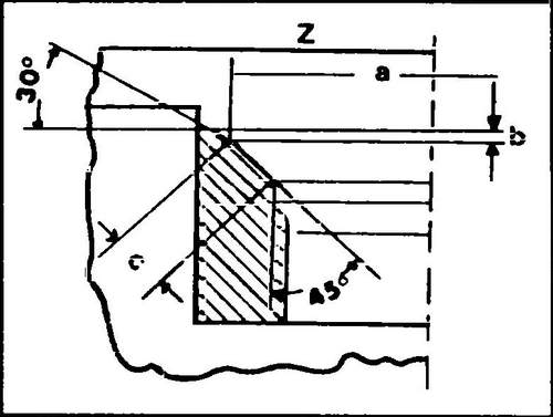
Rice.
Exhaust valve seat dimensions
The minimum distance is 33.8 mm for intake valves and 34.1 mm for exhaust valves.
After subtracting the minimum distance value from the measured value, you will get the maximum allowable processing size, indicated in fig. 79 and 80 with the letter "c". After installing new guides, valve seats must be machined.
♦ Mill a 45º angle and then use a 30º cutter to lightly finish the top edges of the seat to reduce the width of the inlet valve seat to 2.0mm and the exhaust valve to 2.4mm. Finish processing after reaching the working width of the chamfer.
Rice. 81 Measuring the distance between the end of the valve stem and the upper edge of the block head (dimension "A")
♦ After milling the seat, the valves must be lapped. To do this, apply a small amount of abrasive paste to the working chamfer of the seat, put the valve in the guide and rotate the valves, pressing them against the seat with a suction cup (Fig. 82). The lapping of the valves is completed when a continuous matte ring, uniform in width, is formed on the seat and valve, which is clearly visible on both parts.
Rice. 82 Valve lapping
♦ Draw a series of lines with a pencil along the entire contour of the working chamfer of the valve disc at a distance of about 1 mm from each other, and then lower the valve into the seat, press and turn 90º.
♦ Remove the valve and check if the pencil marks have been erased.
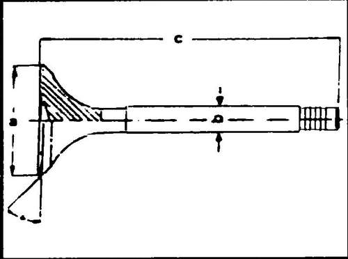
Check the dimensions of the working chamfer. If the dimensions meet the requirements, you can start assembling the block head. ♦ Measure the measurements shown in fig. 83 valve sizes. Replace all out-of-spec valves.
Rice.
83 The main dimensions of the valve a - valve disc diameter, b - valve stem diameter, c - valve length
♦ Pay attention to different valve sizes for individual engines.
♦ If the valve stems show signs of wear, they can be ground.
The inlet valve discs can be ground, provided that after grinding the dimension "b" indicated in fig. 84 will be at least 0.5 mm. Grinding of plates of final valves is inadmissible. They can only be ground or replaced. Block head
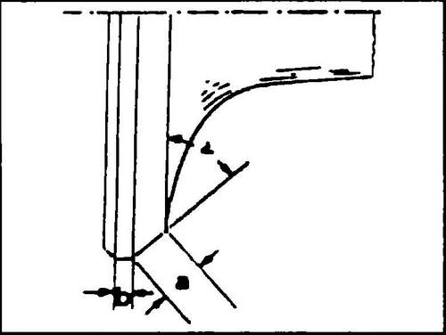
Rice. 84 Valve disc dimensions a = 45º, a - max. 3.5 mm, in - min. 0.5 mm
♦ Check the condition and curvature of the head seat. To do this, measure the gap between the ruler and the surface of the block head with a feeler gauge (see Fig. 85). Place the ruler along, across and diagonally. If the gap is less than 0.1mm, the block head can be used, and if the gap is greater, then the block head must be replaced.
Rice. 85 Checking the seating surface of the block head
Camshaft
All camshafts are marked (see arrow in Fig. 86) to facilitate engine assembly. In place (A) a letter is stamped, and in place (B) a number. When buying a new camshaft, it is convenient to have the old camshaft with you, or at least write off the markings from the old shaft. Only knowing the model code of the Volkswagen Transporter T4 and the engine number, the seller can correctly select the camshaft you need.
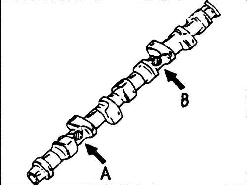
Rice. 86 Camshaft markings
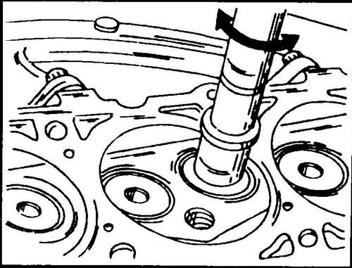
♦ Lay the camshaft with the outer journals on the prisms or fix in the centers of the lathe (see fig. 87) and place the indicator foot on the central journal. Slowly rotating the shaft, read the indicator. If the measured value (runout) is greater than 0.1 mm, the camshaft is considered bent and must be replaced as straightening (editing) is not provided. Check the camshaft bearing journals for visible damage or wear.
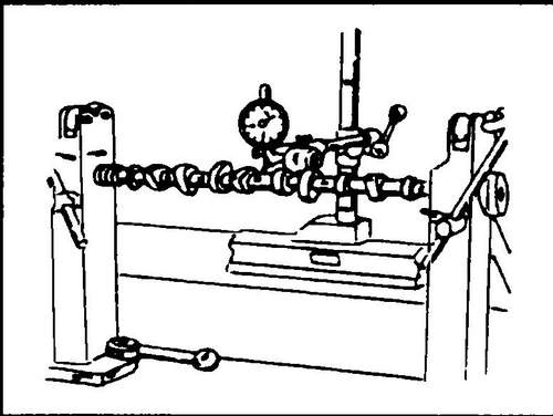
Rice. 87 Checking camshaft runout (at lathe centers)
♦ Use the Plastigage plastic wire method to check the camshaft bearing clearance.
Check after removal of pushers. ♦ Clean the bearing surfaces as well as the bearing journals of the shaft and place the shaft in place.
Lay pieces of "Plastigage" wire across the shaft journals and fit the appropriate bearing caps. Tighten the nuts securing the covers evenly, starting from the middle outwards until a tightening torque of 6 Nm is reached, and then further tighten by 90º. In this case, the camshaft cannot be rotated. ♦ Remove the bearing caps by loosening them in reverse order.
Compare the width of the crushed wire with the template ruler. If the clearance is greater than 0.10mm, then the camshaft, or camshaft and cylinder head, needs to be replaced. ♦ To check the end play, lay the camshaft in the bed of the block head (without tappets) and fasten the front and rear covers. Install the block head on a flat surface. Attach the tip of the indicator to the end of the shaft (see Fig. 88) and move the shaft along the axis until it stops in one direction and the other. The measured gap should not exceed 0.15 mm.
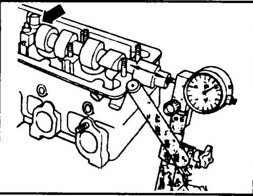
Rice. 88 Measuring camshaft end play
Description of the T4 engine . Specifications Conveyor T4 .