cylinder head
The camshaft lies in the T4 cylinder head on five bearings.
The rear support is used to adjust the axial clearance of the shaft. There is no fourth pillar. In its place, a device (valve) is installed in the oil channel to prevent the outflow of oil from the hydraulic tappets. Inlet valve diameters are not the same on all engines, so please read the information below carefully before proceeding with valve processing. The Volkswagen T4 block head uses hydraulic tappets, so valve clearance adjustment is not required.
Cylinder head Transporter T4
It is unacceptable to remove the block head if the engine temperature is above 40°C.
The block head can be removed from the engine installed in the vehicle in the following way:
♦ Tilt the radiator forward as described in the previous section.
♦ Remove the terminals from the battery.
♦ Drain the coolant.
♦ Remove the air filter.
♦ Disconnect the upper coolant hose.
♦ Disconnect the electrical wires from the devices mounted on the head of the unit.
♦ Disconnect all head-mounted
and body-connected hoses, electrical wires, tie rods, etc.
In vehicles with an exhaust gas recirculation system, disconnect the corresponding hoses from the head of the block. ♦ Remove the upper toothed belt cover.
♦ Loosen the mounting bolts and remove the camshaft pulley together with the drive belt.
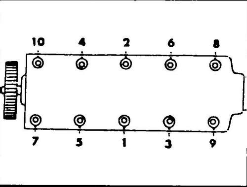
To ensure that the motor timing is maintained, do not remove the belt from the pulley, it is recommended to attach (tie) the belt to the pulley. ♦ Using a socket wrench (12 mm) for TORX bolts, unscrew the bolts securing the head of the block in the reverse order to that shown in fig.
72, remove the bolts. Then remove the block head and its gasket. The camshaft can be removed without dismantling the block head. The covers are removed in the order given in the text.
Rice. 72 The sequence of tightening the block head bolts
T4 Cylinder Head Disassembly
♦ Remove all hardware and disconnect all wires and hoses from the cylinder head.
♦ Install the block head in a vise using the bracket attached to the exhaust manifold studs.
♦ Unscrew the bearing caps numbered 1,3,5 (see fig. 73) in stages and crosswise, and then remove them.
Rice. 73 Numbering of crankshaft bearing caps
♦ Loosen the nuts of covers 2 and 4 step by step in two turns crosswise, and then remove the covers.
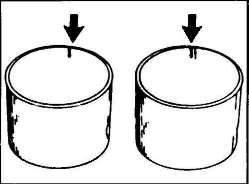
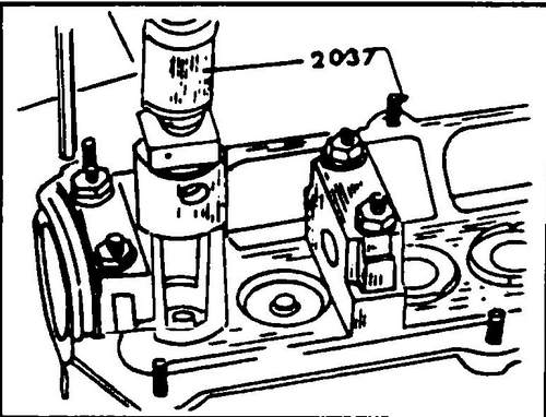
Remove the oil drain valve and camshaft bearing caps. There is an oil seal in the cover No. 1, which is recommended to be replaced. ♦ Remove the pushers. They cannot be interchanged and therefore must be marked with risks on the inside (see fig. 74). Start numbering from the timing drive side. Removed pushers must not be laid on their side. Place them with the working surface (contact with the valve) down so that the oil remains inside. The recommended tool for removing and installing valves is No. 2037. This tool is installed on the cylinder head (see Fig. 75), and serves to compress the valve springs when the valves dry out. The tool plunger must have an outer diameter slightly smaller than the tappet hole, otherwise the valve spring cannot be compressed. Compress the springs just enough to remove the crackers.
Rice. 74 Marking of valve lifters after dismantling from the block head
Rice. Fig. 75 Valve removal with VW special tool
♦ Remove the top plate and springs.
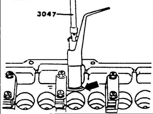
♦ Remove the oil seal, it is disposable and must be replaced, remove the lower spring plate using tool 3047 (see Fig. 76). You can also use internal circlip pliers.
Rice. 76 Removing the lower spring plate using a special tool
Characteristics of the Volkswagen T4 engine . Specifications of the Transporter .


