Installing the block head
♦ Wipe the seating surfaces of the cylinder head and cylinder block.
Place the head gasket with "OBEN" facing up. Be sure to use a new gasket during each assembly. Gaskets for different engines differ from each other and therefore they must be selected from the catalog. For a more accurate installation of the block head relative to the cylinder block, it is necessary to screw it into the holes shown in fig.
92 (8 and 10 in Fig. 92) two guide pins. In the absence of such studs, you can use two studs with the appropriate thread, at the ends of which you need to make slots for a screwdriver. In some cases, the head is installed using guide pins pressed into the block. In this case, the pins described above do not need to be used. During the installation of the Volkswagen Transporter T4 , the valves may rest against the pistons. To avoid this, set the piston of the first cylinder to TDC, and from this position turn the crankshaft a quarter of a turn in the direction opposite to the direction of its working rotation. Install the block head only in this position of the crankshaft.
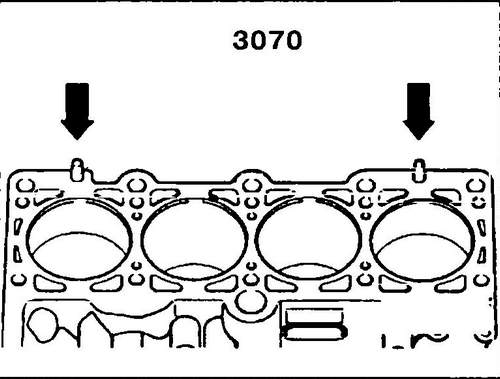
Rice. 92 Installation locations for guide rods
♦ Place the head on the cylinder block and tap it with a rubber or plastic mallet.
♦ Insert and hand-tighten the 8 block head bolts.
Unscrew both mounting guide studs with a screwdriver and screw the block head bolts into their places. ♦ In the order shown in fig.
92, tighten the block head bolts using the method described below. It should be reminded once again that only a multi-faceted wrench, similar to a wrench for bolts with a hexagonal socket, can be used to tighten the bolts, otherwise the bolt heads may be damaged: - tighten all bolts with a tightening torque of 40 Nm in the order shown in fig.
92, - Tighten all bolts in the same sequence with a tightening torque of 60 Nm.
♦ In the sequence above, tighten each bolt exactly one half turn (or two quarter turns).
♦ Reinstall the drive belt and adjust the valve timing.
♦ Place a semi-circular gasket on the block head, and on the other side a semi-circular sealing ring.
Glue both parts on the grease to the surface of the block head. ♦ Install the valve cover, place the gaskets on the studs on the left and right side of the cover, and tighten the nuts step by step and crosswise with a tightening torque of 10 Nm.
♦ Perform all other assembly work in reverse order.
Checking the hydraulic tappets
Improper handling of the hydraulic tappets can damage the engine, so follow the instructions below.
During storage, the pushers must be installed vertically (not laid on their side) with the working surface down.
Pushers always replace with a set as they are not subject to repair and adjustment.
The pusher device is shown in fig. 93.
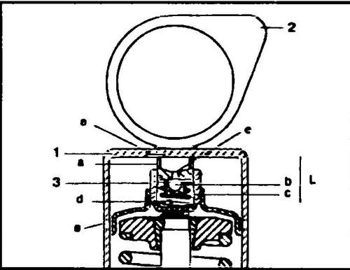
Rice. 93 Hydraulic pusher device
When the engine is running, the poppet (1) is unloaded when the camshaft lobe (2) points upwards.
The spring (d) presses the cup (3) against the end of the valve, and the upper plunger (a) presses the poppet against the camshaft.
In this position, the engine oil enters the working volume (c) through the recess (e) or flows out of it. As soon as the poppet is under pressure from the camshaft cam, the ball valve (c) closes, and the engine oil, trapped in the enclosed space, behaves like a solid body, because. practically does not compress. Thus, the distance with each revolution of the camshaft compensates for the dimensional change in the valve train. By design, hydraulic tappets of different cars differ little, the differences are mainly limited to the presence and location of the oil supply groove and the absence / presence of shims.
Noisy valve operation during engine start is normal.
But if the operation of the valves seems too noisy to you, check the tappets as follows: ♦ Start the engine and let it warm up (the radiator fan will turn on).
♦ Approximately 2 min.
increase the crankshaft speed to 2500 rpm. ♦ If the tappets are still too noisy, you can determine which tappet is damaged (not holding oil pressure) as follows.
After removing the valve cover, turn the camshaft so that the top of the cam of the pusher to be checked is pointing up. ♦ Using a wooden or plastic wedge, push the pusher down (see fig. 94), if the gap between the pusher and the cam is more than 0.1 mm, before the valve begins to open, the pusher must be replaced. After installing new tappets, the engine must not be started within 30 minutes from the moment the assembly is completed, otherwise the valves may hit the pistons.
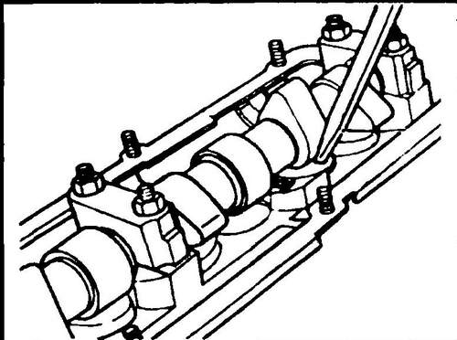
Rice. 94 Checking hydraulic tappets
Volkswagen Transporter engine . VW Transporter specifications .