Removing the crankshaft
In order to remove the crankshaft, it is necessary to remove the engine from the car, as described above.
♦ Make a punch mark on the flywheel and clutch basket to indicate their relative position and facilitate subsequent assembly.
If you plan to replace the basket or flywheel, then it is useless to apply marks. ♦ Remove the clutch basket.
♦ With the flywheel or crankshaft blocked, remove the crankshaft pulley bolts.
In vehicles with a manual transmission, the bolts holding the flywheel are unscrewed by fixing the ring gear with a screwdriver.
However, it is often possible to unscrew the fastening bolts without it (with a jerk). Install a spanner wrench on the bolt at a right angle to the plane of the flywheel and hit the wrench handle sharply with your hand to move the fasteners. You can also use a metal strip with two holes to fix the flywheel. The strip is attached to the flywheel with clutch bolts. Together, holding the engine and unscrew the bolts. Transporter T4 vehicles with automatic transmission manufactured since 1991, the drive disc is dismantled in the same way.
♦ Remove the coolant pump pulley and lower toothed belt guard.
♦ On the outer surface of the belt, mark with paint the direction of its working movement.
♦ Loosen the nuts securing the tensioner pulley, remove the toothed belt from the pulleys and pulley.
After that, the crankshaft cannot be rotated. ♦ Remove the block head together with manifolds.
♦ Remove the oil pan.
♦ Remove the oil pump.
If only the crankshaft needs to be removed, the pistons and connecting rods can remain in the engine block.
Otherwise, remove the pistons and connecting rods (section 2.1.3). If pistons with connecting rods remain in the block, mark the connecting rod caps, remove them and leave them with liners. ♦ Mount the indicator with stand in front of the front of the housing so that the tip of the indicator can be placed against the end of the crankshaft.
Using a large screwdriver, push the crankshaft all the way first in one direction, reset the indicator, and then feed it all the way in the other direction. The indicator readings are the axial clearance of the crankshaft. Write down the resulting value. If the axial clearance is greater than 0.25 mm, it must be corrected during assembly. In the new engine, the liners of the middle main bearing are equipped with thrust half rings. During replacement, as a rule, flanged liners are installed, in this case, thrust rings are not necessary. Thrust half-rings or thrust flanges of the bushings take up axial loads. If you do not have an indicator, you can measure the axial clearance using a set of flat feelers, which are inserted in turn between the end surface of the middle bearing and the crankshaft journal flange (Fig. 111).
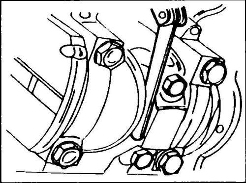
Rice. 111 Measuring the connecting rod clearance on the crankpin
♦ Loosen the bolts securing the front oil seal cover, remove the cover.
♦ Remove the motor intermediate plate, it is centered on the guide bushings.
Remove the bolts securing the rear oil seal cover and remove the cover along with the oil seal and gasket. ♦ Loosen the bolts securing the main bearing caps by loosening them in stages and crosswise, and then remove the caps one by one.
Check if the cap numbers are clearly visible, if necessary, mark the caps with paint or a core. Cover number 1 is located on the side of the belt pulley. ♦ Remove the half shells from the crankshaft journals and place them on the respective main bearing caps.
♦ Carefully remove the crankshaft from the cylinder block.
♦ Remove the rest of the half shells from the engine block. Remove the lower support rings from the middle bearing (if equipped).
Agricultural tractor T40 - traktor-t40.ru . Engine Transporter T4 .