Diesel engine block head repair
Valve Guides
♦ Clean the valve guides with a rag soaked in clean kerosene.
Then install the valves in the same guides in which they were previously located (according to the previously applied marks). ♦ Fasten the indicator with the appropriate stand to the block head of the Volkswagen T4 (see fig. 188). Pull the valve out of the guide so that the end of the valve stem is aligned with the end of the guide and attach the indicator tip to the side surface of the valve disc.
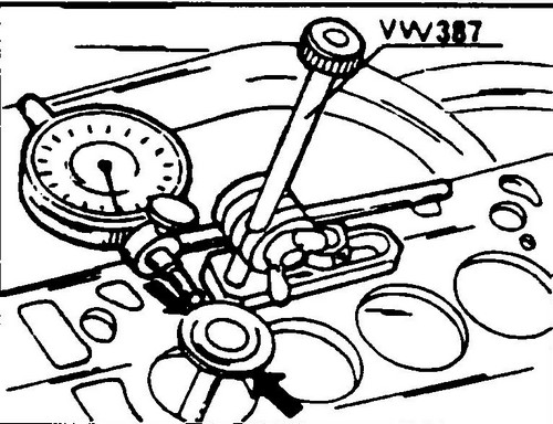
Rice. 188 Valve guide and stem wear check
♦ Rock the valve disc back and forth in the direction shown in fig.
188 and read the indicator. If the play is greater than 1.3 mm, the valve or valve and guide must be replaced. Before proceeding with the replacement of guides, it is necessary to check the general condition of the block head.
A block head with small cracks between the valve seats can be further used after grinding, provided that the cracks are not wider than 0.5 mm. Before installing a new guide, you must remove the old one. If the guide is fitted at the factory, it must be pushed out with a suitable pin from the camshaft side. If the guide has been previously replaced, it can only be pushed out from the side of the combustion chamber, since the guides made as spare parts have a thrust flange. To facilitate installation, the block head can be heated. The rod for installing and removing the guides must have a neck at the end (with a diameter equal to the diameter of the guide hole), which is inserted into the guide (special tool number 10 - 206). On fig. 189 shows the rod upset in the head of the block.

Rice. 189 Installing the valve guide
If you change guides, you must also replace the corresponding valves, which will then need to be lapped into the seats.
Lubricate the new guides and install in the cold head on the camshaft side until the guide shoulder rests against the surface of the block head (only guides supplied as spare parts have a shoulder). After that, do not increase the pressure force, as you can cut off the flange of the guide. After installation, the guide must be expanded to size.
To do this, use a special reamer 10 - 215. In the absence of such a reamer, you can use a simple reamer of the appropriate diameter. The exhaust and intake valve guides pivot to the same 8.0mm dimension. The reamer must be well lubricated with engine oil. After replacing and processing the guides, grind the valve seats to ensure the relative position of the guide and the seat. The dimensions required for processing valve seats are shown in fig. 190. Check all valve seats for signs of wear or pitting. Small traces of wear can be removed with a 45º cutter. If the working chamfers are badly worn, the valve seats must be milled again.
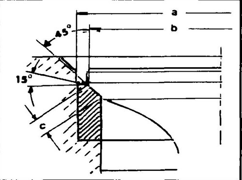
Rice.
190 Valve seat geometry a - valve seat diameter, b - valve seat face diameter, c - valve seat face width
Determination of repair dimensions
♦ Insert the valve into the guide and press firmly against the seat.
♦ Measure distance "A".
This is the distance from the end of the valve to the top edge of the head. ♦ Calculate the maximum allowable milling allowance by subtracting the minimum allowable distance from "A", which is 35.8 mm for exhaust valves and 36.1 mm for intake valves.
This resulting allowance must be maintained during the operations described below - valve seats should be machined while maintaining the width of the chamfer ("C" Fig. 190), which is shown in table 1. To reduce the width of the chamfer, the upper surfaces of the seats must be machined with a cutter with an angle 15º Shown in fig. 190 dimensions are the same in both diesel engines. The above dimensions are mandatory, as they prevent the valves from sinking too deep into the block head, which changes the working force of the return springs and the valve operation.
♦ After milling the valve seats, lap the valves and seats.
Valves
Measure the dimensions of the valves and compare them with the data contained in table 1.
Valves that do not have the required dimensions must be replaced.
If the ends of the valves are worn, they can be sanded, provided that this removes a layer of no more than 0.5 mm. The working chamfer of the inlet valve disc can be machined on a grinding machine.
Dimension "c" should not be less than 0.5 mm. Grinding of exhaust valves is unacceptable. They can only be ground or replaced. Head of the block
The landing surface of the head of the block is checked in the same way as in a gasoline engine.
The maximum allowable curvature is 0.1 mm for a four-cylinder and 0.2 mm for a five-cylinder engine.
If the gap between the ruler and the surface of the head in some place exceeds the specified value, the block head must be replaced. Camshaft
If the measured value is greater than 0.1 mm, the shaft is considered bent and must be replaced. The radial clearance of the shaft bearings is measured in the same way as in a gasoline engine. The same applies to measuring the axial clearance of the camshaft. Fix the indicator on the end surface of the head. In a five-cylinder engine, the sensor can also be mounted on the other side. Move the shaft to one side and the other until it stops and take the indicator readings. The gap should not exceed 0.15 mm. Otherwise, the bearing surface of the bearing cap is worn.
When driving in a car, it is always a pleasure to listen to soulful music - for example, songs by Mikhail Krug . Powerful VR6 engine .