Generator VW Transporter T4
Before starting any work on the charging system, please read the following safety precautions carefully:
♦ Never disconnect the battery or voltage regulator while the engine is running.
♦ Never allow ground to come into contact with field terminals or electrical wires connected to them.
♦ Never swap voltage regulator wires.
♦ Do not ground the regulator, if the engine is running, the regulator will be damaged immediately.
♦ Never remove the alternator without first disconnecting the electrical wires from the battery.
♦ When installing the battery, pay attention to its correct connection to the car's mains (although the terminals are specially made for this purpose in different sizes).
♦ If you are charging the battery without removing it from the vehicle, remove both terminals from the battery.
Checking the
VW T4 on a car If the charging control lamp is on, the generator or voltage regulator or the wires between them may be damaged, or the drive belt may be damaged (stretched, torn).
First of all, you should check the belt, in the second - the wires suitable for the generator. Check alternator V-belt tension.
Further actions can be performed only after removing the generator. Removal and installation of the generator Transporter T4
Depending on the installed engine, the generator can be fixed in various ways.
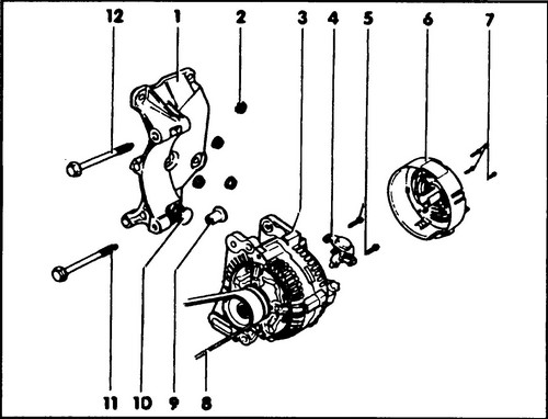
During removal and installation, it is recommended to use fig. 500 and 503. ♦ Remove the battery terminals.
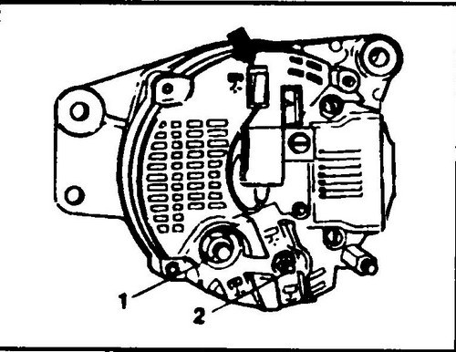
Remove the electrical connector from the back of the generator (Bosch generator) or disconnect the wires (Valeo generator, see Fig. 501). ♦ Loosen the V-belt tensioner and both bolts securing the T4 alternator.
Take the tensioner aside. ♦ Move the alternator against the cylinder block and remove the V-belt.
♦ Remove the bolt(s) securing the generator from below and remove the generator (see fig. 500). However, it is sometimes necessary to raise the machine to gain access.
Rice. 500 Dismantling of the T4 generator - diesel 1.9 release from October 1992
Rice. 501 Generator Valeo
The generator is installed in reverse order.
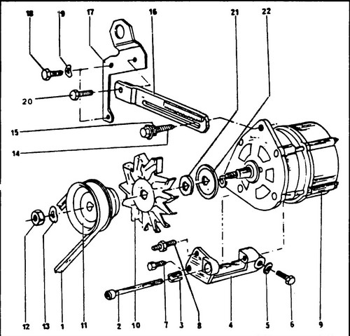
Slide the V-belt over the belt pulleys and tighten the bolt blocking the tensioner plate. Check the V-belt tension and adjust if necessary (this description applies to all engine types). To remove the generator bracket (4) (see. Fig. 502), you must first drain the coolant.
Rice.
502 Mounting the VW T4 generator in a gasoline engine - Bosch generator 1 - V-belt, 2 - “TORX” type bolt, 3 - spacer sleeve, 4 - generator bracket, 5 - washer, 6, 7 - bolt, 8 - stud, 9 - generator, 10 - fan, I - belt pulley, 12 - nut, 50Nm, 13, 19, 22 - washer, 14, 18 - bolt, 35 Nm, 15 - nut for adjusting the V-belt tension, 16 - tensioner bar, 17 - bracket, 20 - bolt, 20 Nm, 21 - spacer
Adjusting the tension of the V-belt
The need to adjust the tension of the belt appears after removing the generator, and also if the V-belt has stretched and its tension has decreased.
After 100 km of run after installing a new V-belt, it is necessary to check
its tension, since the belt always stretches a little at the beginning.
If you hear a characteristic noise in the V-belt area, be sure to check the tension and, if necessary, bring it back to normal. Repair of the Bosch generator
Dismantling
A typical Bosch T4 generator is shown in fig. 503.
Rice.
503 Bosch alternator 1 - nut, 50Nm, 2 - washer, 3 - belt pulley, 4 - spacer, 5 - washer, 6 - fan, 7, 8, 17, 24, 32 - bolts, 9 - front cover, 10 - front bearing, 11 - bearing pressure plate, 12 - spacer ring, 13 - key, 14 - armature, 15 - rear bearing, 16 - stator, 18 - diode board, 19 - insulating plastic washer, 20 - lubricating plastic washer, 21 - back cover, 22 - voltage regulator, 23 - insulating plastic washer, 25 - washer, 26 - spring washer, 27 - washer, 28 - contact nut "D+", 29 - spring washer, 30 - nut, 16 Nm, 31 - capacitor
♦ Loosen the rotor nut and remove the drive pulley, impeller and spacer.
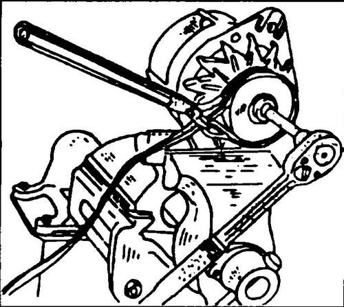
shaft can be supported while loosening the nut with an old V-belt, as shown in fig. 504. A two- or three-legged puller may be required to remove the belt pulley. The pulley diameter is different for different engines.
Rice. 504 Loosening the nut securing the alternator pulley Volkswagen T4
♦ Remove the key from the shaft.
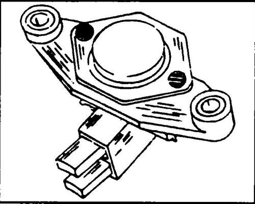
♦ Unscrew the regulator together with the brush holder and take it out.
♦ Mark the position of the front cover relative to the back cover and unscrew both studs connecting the generator panels from the back cover.
Detach the front cover from the body, tapping it lightly with a rubber mallet if necessary. ♦ Remove the generator rotor from the cover using a press or puller (see fig. 505). If the bearing cover is not fixed to the pressure plate during disassembly, the bolts securing the plate may be pulled out. If it is necessary to remove the bearing from the front cover, unscrew the screws securing the pressure plate and remove the bearing by applying force evenly along the axis of the bearing bore.
Rice. 505 Removing anchor front cover
♦ Remove the bearing from the slip ring side.
If you use a puller for this, then its paws should be wound behind the inner ring. ♦ Unsolder the diode board (bridge rectifier) from the starter.
At the same time, to remove heat, it is recommended to hold the wires with tongs between the starter and the soldering point. Diodes must not be overheated. Checking the carbon brushes and brush holders
Check that the brushes fit snugly against the slip rings and that the brushes move freely in the brush holder.
If necessary, clean the brush holder with solvent. If the brushes protrude from the brush holder by 5.0 mm or less, then they should be replaced (see Fig. 506). Attach one wire of the device to the contact ring, and the other to the protrusion (pole) of the armature. If the meter shows an open circuit, replace the armature.
Rice. 506 Protrusion of brushes from the brush holder must be at least 5.0 mm
Checking the rotor (armature)
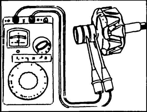
If the slip rings have a dirty surface, wipe them with a cloth soaked in solvent. Polish possible scratches with the finest sandpaper. Armature insulation is checked with an ohmmeter.
Rice. 507 Checking the generator winding Conveyor T4
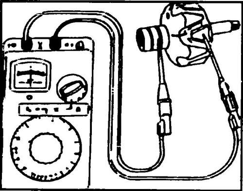
In order to check for breaks, attach both probes to the slip rings, as shown in fig. 508. The reading of the ohmmeter should be in the range of 2.8 - 3.0 ohms. If the device shows "infinity", then there is a break in the circuit. If the resistance is “zero”, then there is a short circuit in the circuit. In both cases, the anchor of the generator Transporter T4 should be replaced.
Rice. 508 Check armature windings
Checking the stator
In the event of a short circuit to ground, damage is very easy to determine due to severe overheating. In other cases, check the resistance with an ohmmeter by applying one end to the rings of magnetic sheets, and the other in turn to the four ends of the stator winding (see Fig. 509). In order to check for an open in the stator windings, check the four wires of its winding in turn. If the device does not show anything, then there is an open circuit in the circuit. The resistance of individual windings should be 0.10-0.11 ohms.
Rice. 509 Check for open stator windings
Assembling the T4 generator Assembly
is carried out in the reverse order to disassembly.
Repair of the Valeo generator
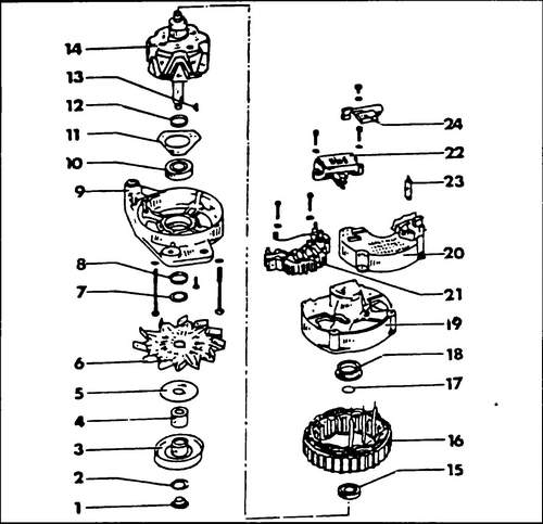
In fig.
511 shows the device of the generator. Using this figure, the generator can also be dismantled. Checking the Valeo generator is carried out similarly to checking the Bosch generator, the following conditions must be observed:
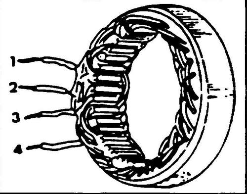
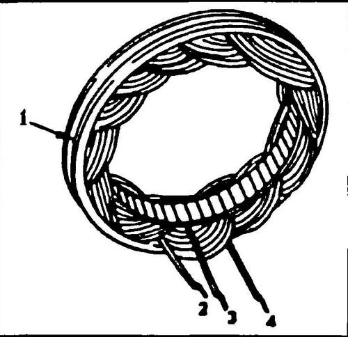
When checking for a short circuit of the stator windings, one wire of the ohmmeter must be attached to the ring of magnetic conductors (1, Fig. 510), and the second - in turn to the ends of the three wires ( 2), (3) and (4).
Rice. 510 Short circuit test
To check for breaks in the stator windings, check the three stator wires in turn (Fig. 511) If the device does not show anything, then there is a break. The resistance in the circuit should be 0.10-0.11 ohms.
Rice.
511 Generator Valeo (65A) Volkswagen Transporter T4 1 - nut, 40 Nm, 2, 5, 7 - washers, 3 - belt pulley, 4 - spacer sleeve, 6 - fan, 8, 12 - spacer rings, 9 - front cover, 10 - front bearing, 11 - bearing pressure plate, 13 - key, 14 - rotor (armature), 15 - rear bearing, 16 - stator, 17 - metal ring, 18 - plastic bushing, 19 - back cover, 20 - closing cover , 21 - plate with diodes, 22 - voltage regulator, 23 - hairpin, 24 - capacitor
