Starter VW Transporter T4
VW Transporter T4 cars use different starters, depending on the power and design features of the engine. The table at the beginning of this chapter lists the starter numbers for individual engines.
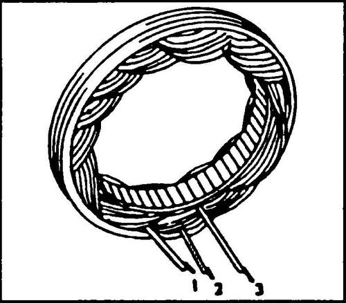
Rice. 512 Checking the stator windings for an open
Rice. 513 Brushes must protrude from the brush holder by at least 5.0 mm
Checking the VW T4 starter
To check the starter, it is necessary to connect terminal "30" (large terminal) and "50" (terminal to the right of the large one) with a copper wire with a cross section of at least 4 mm2 (welding wire).
If the starter works well, check the wire to the starter from the battery.
If the starter does not mesh with the flywheel, the starter must be removed and inspected. Starter Removal and Installation Transporter T4
♦ Disconnect the battery terminals.
♦ Raise the front of the vehicle on stands.
♦ Disconnect harnesses from alternator and ignition switch.
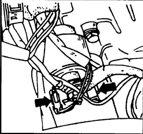
After installing the starter, secure them in place. ♦ Remove both connectors (black and white) (see fig. 514), disconnect the wire of the alternator “D+” terminal and the wire to the battery positive (this starter terminal is shown in fig. 514 on the right side).
Rice. 514 Starter contacts
♦ Loosen the nuts and bolts securing the T4 starter.
♦ Remove the starter.
♦ Install the starter in reverse order.
Dismantling and assembly of a starter Volkswagen T4
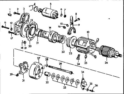
In fig. 515 shows a typical Bosch starter device with an intermediate bearing disc installed in VW T4 cars.
Rice.
515 Starter T4 1 - starter bushing, 2 - bolt, 3 - front cover, 4 - small parts., 5 - solenoid relay, 6 - spring washer, 7, 17, 19 - M8 nuts, 8 - drive lever rod, 9 - drive lever, 10 - stator winding, 11 - M10 bolt, 12 - washer, 13 - restrictive ring, 14 - bendix, 15 - spring washer, 16 - Mb nut, 18 - circlip, 20 - intermediate bearing disc, 21 - bushing bendix slides, 22 - spring, 23 - connecting sleeve, 24 - pole extension screw, 25 - carbon brush, 26 - armature, 27 - collector cover, 28 - washer, 29 - connecting bolt, 30 - pressure spring, 31 - brush holder, 32 - sliding sleeve on the collector side, 33 - set of washers, 34 - cover, 35 - spring washer, 36 - bolt, M4
If it is necessary to remove the starter Transporter T4, proceed according to the following recommendations.
♦ From the front of the solenoid relay, unscrew the fastening bolts, disconnect the relay from the drive lever and remove it.
♦ Remove the back cover.
♦ Loosen the manifold housing bolts.
♦ From the end of the armature shaft, remove (with a screwdriver) the circlip, remove the washers and the manifold housing.
If necessary, disconnect it with a screwdriver. ♦ Remove both carbon brushes from the brush holder and then remove the brush holder.
♦ Remove the starter housing from the anchor along with the stator winding.
♦ Pull out the pivot, which is the rotary axis of the drive lever (bendix), remove the lever.
♦ Remove the gasket from the front cover, paying attention to the position in which it was installed.
♦ The brushes are soldered to the starter windings and in order to replace these brushes, they must not be soldered off, but must be replaced together with the stator winding.
If necessary, proceed as follows: ♦ Remove the four screws securing the stator pole extensions (fig. 516).
Rice. 516 Removing the pole extension
♦ Remove the winding together with extensions from the housing and then disconnect the pole extensions.
♦ When removing the bendix or anchor, use fig. 517.
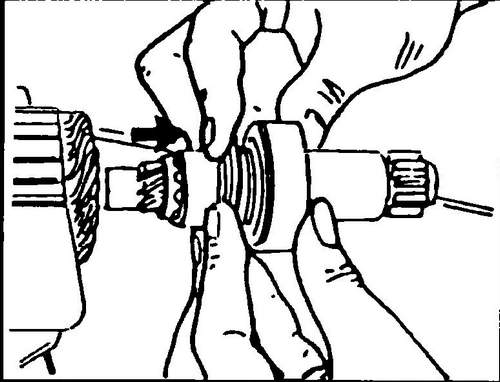
Rice. 517 Retaining ring
♦ Using a tube of the correct diameter, push the restrictor ring down until you have access to the snap ring (see arrow).
♦ Remove the circlip from the armature shaft groove.
♦ Remove any burrs from the end of the armature shaft.
♦ Fix the anchor in a vise and remove the bendix from the anchor shaft (fig. 518).
Rice. 518 Removing the bendix and armature shaft
The collector should be smooth, without scratches.
If the manifold is badly worn, it can be machined on a lathe, maintaining a certain minimum diameter. Bendix should not understand.
If damaged, it must be replaced as an assembly. The starter Transporter T4 is assembled in the reverse order.
The minimum thickness of the brushes is 13 mm, if they need to be replaced, then crush the old brushes with tongs and beat off the ends of the braided wires. Settle the wire on a new brush and fan out the ends of the wires from the blind side. ♦ Holding the wire from below, solder it to the brush on the other side.
During assembly, adhere to the following recommendations.
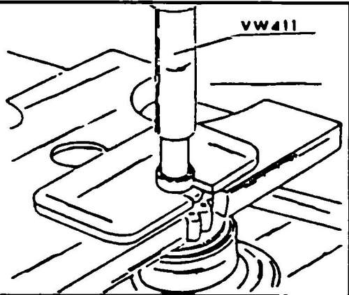
♦ Fit the bendix and then the limiter ring onto the armature shaft and seat the spring ring into the groove of the shaft. Install the restrictive ring on the press on the spring ring, applying the press force to the end of the armature shaft (see Fig. 519).
Rice. 519 Installation of the limit ring on the snap ring
♦ If necessary, replace the bearing bush in the manifold housing (it can be easily removed).
Before installing a new bushing, heat the manifold housing for 5 minutes in hot oil. ♦ The places marked with letters in fig. 520, coat with sealant.
Rice. 520 Places marked with letters, cover during assembly with sealant
The axial clearance of the armature should be 0.1-0.3 mm.
It can be adjusted with washers on the rotor shaft between the manifold housing and the "C" shaped retaining spacer.
