brake pressure regulator
The brake pressure regulator is attached to the body from the bottom of the Transporter T4 and is connected by two springs to the transverse two-arm regulator lever.
On fig.
449 shows the placement of parts related to the regulator. The brake pressure regulator must be adjusted after each replacement of the lever, and also if for any reason, for example, for repairs, the brackets for the spring hooks (6) (see Fig. 449) were removed without indicating their position relative to the lever. In this case, at least a pre-adjustment of the controller is required.
Rice.
449 Rear brake pressure regulator 1 - rear brake pressure regulator, 2 - mounting nut, 3, 4 - bolt 20 Nm, 5 - nut, 6 - bracket for spring hook, 7 - spring (pay attention to installation position), 8 - latch , 9 - rocker arm, 10 - rubber limiter, 11 - trailing arm
Although customization may seem quite complicated, it can be done with only public tools.
Rice.
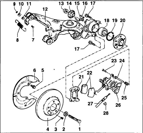
450 Rear disc brake device 1 - bolt, 150 Nm + 90º (only for four-wheel drive vehicles), 2 - washer, 3.16 - bolt type "Tox", 10 Nm, 4 - brake disc, 5 - bolt, 10 Nm, 6 - brake shield, 7 - bolt, 8 - adjuster spring, 9 - nut, 20 Nm, 10 - lock washer, 11 - locking clip, 12 - suspension arm, 13 - self-locking nut (only for four-wheel drive vehicles), 200 Nm, 14 - disc, 15 - speed sensor, 17 - bolt, 110Nm, 18 - wheel bearing, 19 - retaining ring, 20 - wheel hub, 21 - brake caliper, 22 - brake pads, 23 - bolt, 35 Nm, 24 - guide , 25 - rubber cap, 26 - brake caliper, 27 - handbrake cable, 28 - spring clip
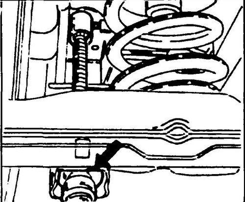
Remove the rear shock absorber as described in chapter 7 and in its place install a threaded rod with an eyelet allowing it to hang on the bolt that secures the shock absorber from above. Put one of the bushings removed from the shock absorber, as well as the washer, on the threaded rod so that the rubber bushing is between the washer and the lever, then screw on the nut. On fig. 451 shows a special tool.
Rice. 451 Special tool fitted instead of shock absorber
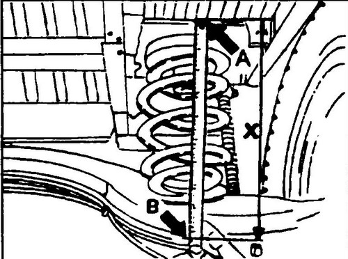
Now you need to pre-tension the lever, that is, to obtain a certain size (“X”, Fig. 452) between the base plate of the body (A) and the upper edge of the spring seat (B) in the trailing arm. This size differs in vehicles of different groups. It can be read on a sticker placed on the door pillar. The first series of cars were released without this sticker. In such vehicles, the "X" dimension is set based on the color coding of the suspension springs.
Rice. 452 Measuring the height of the rear of the car to adjust the regulator
You can find springs marked with the following colors:
Dimension "X", mm (see fig. 453)
Green 285
orange 260
white 250
violet
(lilac) 275
Brown 285
blue 240
To set the desired "X" dimension, tighten the nut on the threaded rod until the lever is raised high enough.
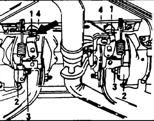
♦ Now set the rocker (4) (fig. 453) or (9) (fig. 449) to a horizontal position. For installation, both rubber stops 1 (Fig. 453) must be turned up so that they touch the lever, but do not put pressure on it.
Rice. 453 Brake pressure regulator setting
♦ Move one of the spring hook brackets (2) down so that on the other side there is a gap between the limiter (1) and the rocker arm (4).
♦ Loosen the second spring fixing bracket and pull it down until the rocker is in a horizontal position again.
♦ Screw in both stoppers (1) completely so that there is as much clearance as possible between them and the rocker arm (4).
Now you need to fine-tune using pressure gauges.
After adjusting with a front brake pressure of 50 bar (5 MPa), the rear brake pressure should be 20 bar (2 MPa). This will ensure that the front wheel braking is stronger than the rear wheels (design code requirement). To adjust the regulator, the pressure in the right front and left rear brake cylinder is measured. Adjust as follows: Screw both stops (1, Fig. 453) in completely.
♦ Mark the position of the spring mounting brackets relative to the lever with a felt-tip pen or adhesive tape.
♦ Unscrew the screws (3) and move the spring bracket (2) down to increase the pressure or up to decrease it.
♦ A bracket adjustment of 1 mm corresponds to a pressure change of approximately 4 bar (0.4 MPa).
Often, for adjustment, it is enough to rearrange only one bracket, provided that the distance from the horizontal position of the rocker arm is no more than 4 mm. ♦ Bolt (3) tighten to the recommended tightening torque.
♦ If necessary, you can unscrew the bolt (3) on the other side and adjust the position of the second spring mounting bracket.
♦ Remove the threaded rod and install the shock absorber in its place as described in chapter 7.
Removing and installing the brake pressure regulator is a very simple operation, but the position of the spring mounting brackets must be marked to avoid the above adjustment. Install the new regulator and tighten the spring clips in the marked position. Make sure that the hydraulic pipes are connected to the correct ports on the regulator. Bleed the brake system.


