Backstage - gearbox control mechanism
Dismantling the VW T4 yoke
♦ Set the selector lever to neutral position, apply the parking brake.
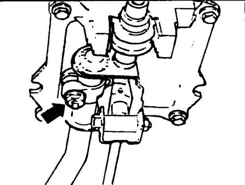
♦ Loosen the clamp (see arrow fig. 350).
The shift arm selector rod must move freely along the guide pin of the arm 1 (see Fig. 348). ♦ Remove the shift handle (1) and its bellows (2) (see Fig. 347).
♦ Remove the frame (4) with the boot (3), the boot was not installed on all models.
When assembling, direct the inscription “VORN”, which is on the cover and on the frame, towards the engine. ♦ Unscrew the grub screw (12) that secures the stop (13) to the lever stem (16).
♦ Remove the stop, spring (14) upwards.
♦ Loosen the nut (10), knock out the axle (9), disconnect the rear shift rod (8).
♦ Disengage the shift lever (16) from the support pin (16) by pulling downwards and remove the lever from the bracket (1).
Try not to lose your finger. Replace damaged and worn parts. If the bushing (17) is worn, the pin (18) will have to be knocked out, after which the bushing can be removed from the lever. Assembly is carried out in the reverse order.
Lubricate all working surfaces with a molybdenum disulphite based lubricant. When installing the stop (13), the locking screw must fit into the hole on the stem.
Adjustment
Signs of correct adjustment of the shift levers are:
- flawless gear shifting and quiet operation of the shift actuator.
- ease of movement of the shift lever.
♦ Set the selector lever to neutral position, apply the parking brake.
♦ Loosen the clamp (see arrow in fig. 349). The selector arm selection rod must move freely along the guide pin of the arm 7.
Rice. 349 Adjusting clamp
♦ Remove the shift handle (7) and its bellows (4) (see Fig. 347).
♦ Remove the frame (5) with boot (8), the boot was not installed on all models. When assembling, direct the inscription “VORN”, which is on the cover and on the frame, towards the engine.
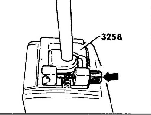
Rice. 350 Setting the pattern
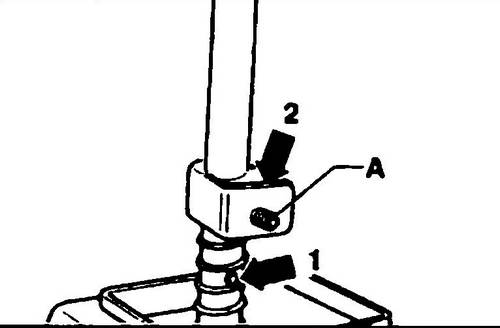
♦ Align (see fig. 351) the flat surface of the stop (14, fig. 347) - it must be parallel to the edge of the frame (5, fig. 347). The stop screw must then enter the hole in the lever (see. Fig. 352).
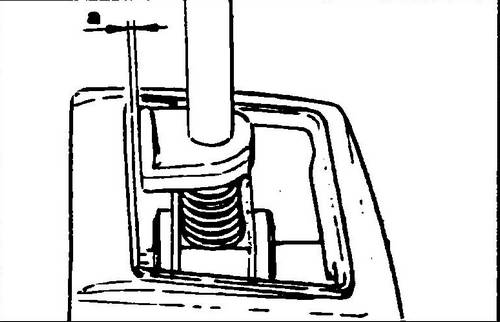
Rice. 351 Gap check
Rice.
352 Stop screw hole for fastening the stop: 1 - hole, 2 - stop
♦ Insert the template into the opening of the yoke housing and fix it with the screw (see fig. 350).
♦ Place the selector rod without tension on the pin of the shift bracket (box in neutral position) and after tightening the clamp to 20 Nm, fix the assembly.
This completes the adjustment. ♦ While pulling the shift lever back, loosen the screw and remove the template.
In the absence of a template, adjustment can be made by trial and error.
Checking the operation of the T4 link
♦ Place the shift lever in neutral opposite 3-4 gears.
The lower part of the shift lever, located below the bend, should be in a vertical position.
♦ With the clutch depressed, start the Transporter T4 .
After a pause of about 10 seconds, necessary for the input shaft of the gearbox to stop, change all gears several times. At the same time, pay attention to the operation of the reverse gear lock. If it is still difficult to shift gears when re-passing any gear, proceed as follows: - Engage first gear.
- select the gap in the shift drive, for which the shift lever is pressed to the left with the first gear engaged with a little effort.
- the distance from the stop of the shift lever to the stop of the backstage body in this position should be a = 1.3-2.3 mm (Fig. 351) -
if the distance exceeds this value, turn off the gear and repeat the adjustment of the drive.
♦ Check the ease of engagement of individual gears. If any gear is hard to engage, it is necessary to find the correct position of the mechanism. This can be achieved by moving the connecting rod to one side or the other.
Transmission Volkswagen Transporter T4 . Clutch Volkswagen T4 .


