Axle drive - removal and installation (front-wheel drive models)
On both sides of the vehicle Transporter T4, the same drive axle shafts are installed.
In order to remove the axle shaft, and also, if it is necessary to repair the front suspension, it is necessary to install supports that unload the torsion springs or loosen the torsion bar loading adjusting bolt (42, Fig. 378), since as a result of the initial stress, the upper transverse levers are pressed down. Before proceeding with the dismantling of the axle shaft, it is necessary to stock up on such supports in advance (special supports N 3250). The supports must be installed before the front of the vehicle is raised. Install the outriggers so that the support surface (A) is under the upper control arm (1) and the V-shaped notch (B) rests on the front suspension cross member.
If the car is loaded, it is necessary to unload it or raise the front of the car so that the supports can be installed.
After dismantling the axle shaft, the wheel hub is not fixed in the axial direction by anything. The car must not be rolled because of the danger of wheel coming off the hub. If necessary, install the outer CV joint, after which the hub will be fixed.
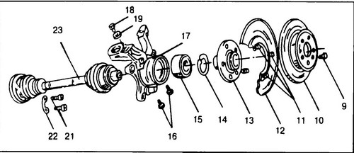
Rice.
370. Front wheel hub device 9 - disc mounting screw, 10 - brake disc, 11 - screws, 5 Nm, 12 - brake shield, 13 - wheel hub, 14 - retaining ring, 5 - wheel hub bearing, 16 - bolts, 55 Nm , M10x20, 17 - wheel hub housing, 18 - bolt, 60Nm, Ml2x1.5x22, 19 - washer, 20 - hub mounting bolt, 280Nm, 21 - CV joint mounting bolts, 70Nm, 22 - backing plate, 23 - half shaft T4
Removing the Axle Conveyor T4
♦ Fit the spacers to secure the upper front suspension arm.
♦ Remove the trim cap and loosen the wheel nuts.
Turn away a bolt (1) fastenings of a nave of a wheel to a half shaft. The bolt is very tight, so the car must be on the ground when it is pulled out. Engage first gear and put the car on the handbrake. The bolt is disposable and will need to be replaced during assembly. ♦ Raise the front of the vehicle and place on stands.
It is not necessary to remove the wheel when replacing the drive axle, but if it is removed, there will be much more room to work. ♦ Remove the engine crankcase protection.
♦ Remove the mounting bolts and disengage the wheel hub housing from the lower wishbone (in this version the ball joint remains on the lower wishbone).
Otherwise, you can unscrew the nut securing the ball joint pin and knock the pin out of the lower arm. In this case, the ball joint will remain on the hub housing (on the steering knuckle). ♦ Remove the shock absorber/tie rod and stabilizer bolt.
♦ Loosen the bolts securing the inner CV joint, for this you need an 8 mm socket wrench.
Depending on the year of manufacture, there may be bolts with an internal six or dodecahedron, as well as bolts with only left or left / right threads (different on the sides of the car). ♦ Disconnect the half shaft from the gearbox.
♦ Compress the shock absorber until it stops.
♦ Remove the axle shaft from the wheel bearing housing.
Installing the T4 axle shaft
♦ Before installing the axle shaft splines, clean with a rag soaked in gasoline to remove oil and grease, and repair any damage to the protective coating of the axle shaft.
♦ Insert the axle shaft into the wheel hub and secure with the old bolt.
Do not tighten the bolt. ♦ Attach the axle shaft to the gearbox output shaft flange.
Screw in the bolts securing the inner CV joint and tighten the bolts in stages until a torque of 80 Nm is reached. Do not forget to put washers under the bolts, otherwise the CV joint flange will be damaged. Insert the shock absorber / connecting rod mounting bolt into place and tighten to 160 Nm. ♦ Connect the lower ball joint to the wheel hub housing and tighten the new nut to 110 Nm (manual transmission) or 55 Nm (automatic transmission).
♦ Install the crankcase guard.
♦ Unsupport the vehicle.
♦ Replace the hub-to-axle bolt and tighten the new bolt to 150 Nm, then 1/4 turn (90º) further. Secure the vehicle as described above.
