Disassembly of the half shaft
CV joints are subject to replacement only as an assembly, but, despite this, each CV joint can be disassembled and the wear of its parts can be checked. Due to the fact that the CV joints and their covers are stuffed with grease, stock up on a large amount of rags and new grease (with molybdenum disulphite) to replace. The outer and inner CV joints have a different design. The outer CV joints of vehicles with ABS are different from those of conventional models, the inner CV joints are the same on all Transporter T4 .
♦ Remove the axle shaft as described above.
Clean the axle shaft. ♦ Both CV joint clamps are non-separable, so cut them off or cut them with wire cutters.
Slide the covers from the hinges onto the axle shaft. ♦ Press the outer CV joint off the axle shaft.
To do this, screw a bolt with a long thread M16 or puller 3207 into the end of the hinge shaft until it stops in the axle shaft (see. Fig. 372). ♦ Remove the gasket (7) from the hinge.
♦ To remove the inner joint, remove the circlip (8).
♦ The inner joint can be easily removed from the shaft if the splines are not damaged.
If necessary, correct the slots with a needle file or use a press. After removing from the axle, carefully wipe the CV joint covers, damaged, old (with cracks) covers must be replaced. ♦ Fit new boots with clamps on the shaft.
If desired, screw clamps designed for cooling system hoses can be used. Wire is not recommended. ♦ Assemble the parts (5), (12) on the shaft according to fig. 371.
Rice.
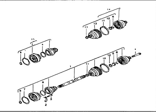
371 Drive shaft device 1 - half shaft assembly, 2 - shim, 3 - mounting bolt, 70Nm, 4 - hub mounting bolt, 5 - spacer ring, 6, 8 - circlip, 7 - gasket, 9, 10, 11 - clamps, 12 - washer, 13 - cover, 14 - outer CV joint, 15 - inner CV joint

Rice. 372 Dismantling the CV joint of the half shaft.
♦ Install a new circlip (6) in the shaft groove.
♦ CV joints, after checking (see below), fill with grease based on molybdenum disulphite, or, at worst, with Li-tol grease in an amount of about 120 g. At the same time, try to apply more grease to the ball area. Distribute approximately 40 g of grease
♦ If only the boot is being replaced, you do not need to change the entire lubricant, add grease directly into the boot and on top of the
joint . until it stops (until the circlip (9) is fixed).
♦ Press the inner joint up to the stop using a copper hammer or a press.
♦ Insert the circlip (16) into the groove of
the shaft. degreasing the appropriate surface.This gasket can be made independently using a "paper" juice bag as a material.On cars of later years of production, on the outer CV joints, instead of rubber, more durable polystyrene covers are installed.
The covers are fastened with stainless steel clamps. The installation of such covers (with appropriate clamps) on cars of an earlier production is possible only with a corresponding replacement of the CV joint. ♦ Place a rubber boot on the CV joint and tighten the fastening clamps on the large diameter.
♦ When installed on the hinge body, the cover is often pressed through.
Therefore, after installation, you need to slightly lift the edge of the cover on the side of the small diameter with a screwdriver and thereby ensure the alignment of the shape. ♦ Tighten the clamp on the small diameter.
♦ Install the axle shaft.
When dismantling the axle shafts on vehicles with automatic transmission - additionally.
♦ Disconnect the multifunction switch connector.
♦ Unfasten the rear silent block to the front axle carrier.
When dismantling the axle shaft, it is necessary to slightly forward the power unit.
For cars manufactured between August 1991 and June 1992 with automatic transmission, the inner CV joints on the left and right are fastened with different bolts.
The right axle shaft is fastened with bolts M 10x48, strength class 12.9, head with internal slots (type "Togh"), the left half shaft is also fastened with bolts of the "Togh" type, but M 10x45 in size, strength class 10.9.
During repairs, it is imperative to install bolts with a strength of 12.9. For vehicles manufactured prior to June 1992, the bolts must be shortened to 45mm to allow the CV joint to be fitted to the gearbox housing.
Bolts with a strength of 10.9 must never be tightened with a torque of 70 Nm. ♦ Attach the rear silent block to the front beam with a torque of 45 Nm.
♦ Connect the multifunction switch connector.