Checking the high voltage converter
The high voltage converter is located in the engine compartment on the left in front of the battery of the Transporter T4 . Bosch voltage converter (see Fig. 288)
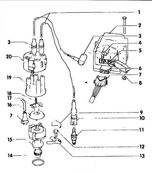
Rice.
288 Ignition distributor / high voltage converter - engine 2.0 1 - high voltage wires, 2 - high voltage converter, 3 - cap with resistor, 0.6 - 1.4 kOhm, 4 - terminal No. 4, 5 - terminal No. 1, 6 - terminal No. 15, 7 - connector, 8 - nut, 10 Nm, 9 - bolt cap (12), 10 - spark plug cap shield, 4-6 kOhm, 11 - spark plug, 80 Nm, 12 - mounting bolt, 85 Nm, 13 - clamping bar, 14 - sealing ring, 15 - ignition distributor, 16 - dust screen, 17 - rotor (slider) R1 (0.6 -1.4 kOhm), 18 - carbon contact with spring, 19 - cover distributor, 20 - screen.
combines an ignition coil, a switch and a power amplifier in one housing, and has an initial resistance in the electronic circuit, which ensures that the required voltage will be in the high-voltage circuit if a voltage drop occurs in the car's network as a result of the starter's action.
The ignition coil is not subject to disassembly and repair, however, you can check the resistance of the primary and secondary windings using a special tool. Check
♦ Disconnect the connector and high voltage wires from the converter.
♦ Connect an ohmmeter to terminals (1) and (15).
The normal resistance value is 0.5-0.7 ohms. ♦ If the measured resistance is not correct, the high voltage converter must be replaced.
The easy way
If you suspect that the inverter is the cause of the problem, use a new inverter in place of the old one.
In this case, it is necessary to use a converter that matches the ignition system installed in the car. It should be remembered that converters often do not show any defects until they warm up to operating temperature.
Therefore, checking in a cold state does not always give reliable results. The insulating cover of the inverter must be cleaned regularly to avoid current loss and flashover. Checking the secondary resistance of the ignition coil
♦ Connect an ohmmeter to terminals (15) and (4) (see fig. 289).
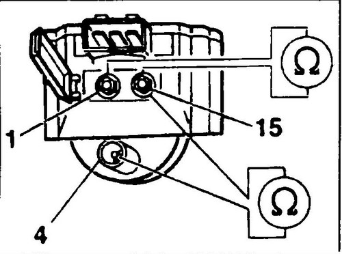
Rice. 289 Scheme for checking the windings of the ignition coil
The normal value of the resistance of the secondary winding is 3-4 kOhm.
♦ If the measured resistance is not correct, the high voltage converter will have to be replaced.
Checking the presence of supply voltage
♦ Connect a voltmeter to pins (1) and (3) of the converter harness connector (see Fig. 292).
♦ Switch on the ignition.
The device should show a voltage of 12-14 V. Otherwise, it is necessary to find and eliminate an open circuit. ♦ Disconnect the fuel injector starter connectors and injector harness connector.
♦ Connect a test lamp to pins (2) and (3) of the converter harness connector.
♦ Switch on the ignition.
The lamp should flash. Otherwise, it is necessary to replace the Hall sensor or, if it is in good condition, the microprocessor module. ♦ Connect a voltmeter to terminals (1) and (15) of the high voltage converter (see fig. 289).
♦ Switch on the ignition.
Normal voltage value: at least 2V, after 1-2 seconds the voltage should drop to zero.
Otherwise, the converter must be replaced. ♦ Connect the fuel injector starter connectors and the VW T4 injector .
Volkswagen T4 fuel tank replacement . Digifant system .