Ignition distributor with Hall sensor
One of the main factors that ensures the correct operation of the Transporter T4 is the speed of its crankshaft.
The Hall sensor (see Fig. 288, 290, 291), located inside the ignition distributor, sends information about the crankshaft speed and TDC position to the microprocessor module.
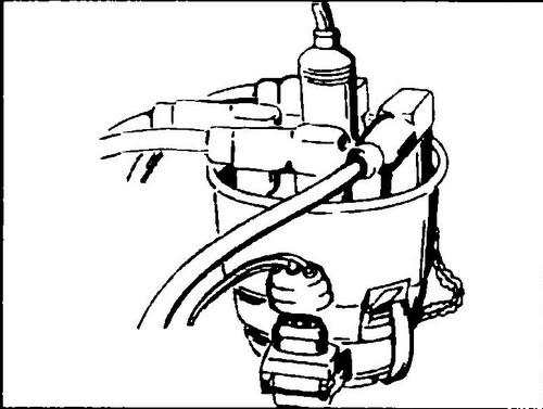
Rice. 290 Ignition distributor

Rice. 291 contact group ignition distributor
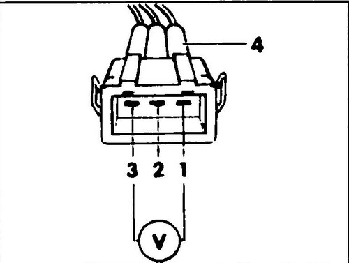
Rice. 292 Supply voltage test circuit
How it works
The electrical impulse required to open the low-voltage circuit is generated by a sensor located in the distributor.
A cylinder with rectangular slots rotates in the gap between the permanent magnet and the sensor. Grooves 4, according to the number of cylinders. At the moment when the groove is between the sensor and the magnet, a current is generated on the sensor. The solid section of the cylinder shields the sensor from the opposite magnet, as a result of which no current is generated. The sensor measures the change in the magnetic field and sends a current pulse to the electronic module, which opens the low voltage circuit. One revolution of the ignition distributor axis corresponds to four Hall sensor pulses, which are received by the microprocessor module as information about the crankshaft speed.
Note: If the microprocessor module does not receive a speed signal, the power supply to the electric fuel pump T4 .
Replacing the fuel tank T4 . T4 injector device .