Hall Sensor
Checking the supply voltage
♦ Disconnect the connector from the Hall sensor (on the ignition distributor) and connect a voltmeter to the external contacts (see Fig. 297).
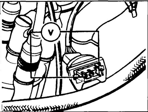
Rice. 297 Checking the voltage supply to the Hall sensor
♦ Switch on the ignition.
The normal voltage on the contacts is at least 10 V. If the voltage is not normal, then the microprocessor module is most likely damaged.
♦ Switch off the ignition.
Checking the Sensor
♦ Disconnect the connectors from the T4 fuel start injector and injector harness.
♦ Remove the rubber insert from the Hall sensor connector and connect the connector to the sensor.
♦ Connect a test lamp between the middle and outer pins of the Hall sensor connector.
♦ Engage the starter.
The control lamp should flash. Otherwise, the Hall sensor is faulty and the ignition distributor will have to be replaced. ♦ Connect the starter injector and injector harness connectors.
Adjusting the ignition timing
The ignition timing is checked at an engine speed of 2000 - 2500 rpm.
All vacuum hoses must be in place.
The flywheel has a mark for setting the ignition. The tongue on the flywheel housing is a reference mark. ♦ Check the XX frequency and adjust if necessary.
♦ Connect the stroboscope according to the vehicle manufacturer's instructions for the Transporter T4 .
♦ Start the engine and let it warm up to operating temperature.
After turning on the fan, remove the connector from the temperature sensor. ♦ Increase the engine speed to 2000-2500 rpm and direct the strobe light into the control window of the flywheel housing.
If the ignition timing is between 4 and 8 degrees before TDC, no adjustments are needed. If the measured ignition timing is outside this range, it must be adjusted again. In this case, it is necessary to achieve the installation of the ideal value of 6º ± 1º before TDC. To adjust the ignition timing, loosen the lock plate and turn the ignition distributor.
In the direction of rotation of the distributor, you can find out in which direction the ignition point “shifts”. ♦ Tighten the bolt securing the lock plate.
♦ Replace the temperature sensor connector and rev the engine to maximum three times and check the ignition timing again.
♦ Let the motor run at frequency XX and after turning on the fan, remove the connector again.
♦ Set the engine speed to 2200 rpm, determine the ignition timing and record it.
♦ Reduce the motor frequency to XX frequency and re-insert the connector into the temperature sensor socket.
♦ Increase the speed again to 2200 rpm and re-adjust the ignition.
The ignition point should now be 20°±3º ahead of the ignition point measured with the connector removed. If the same results are obtained with the connector pulled out and not pulled out, the electrical wire suitable for the connector may be broken or the microprocessor module may be damaged.
Digifant injection system . Main technical characteristics of T4 .