Replacing the timing belt of a diesel engine 2.4 l
The timing drive device of the 2.4 liter engine of the Volkswagen Transporter T4 is shown in fig. 203. All work on the timing drive must be carried out very carefully and carefully, as incorrect installation of the toothed belt will cause immediate engine damage. Also, rotating the camshaft or crankshaft without a toothed belt will damage the valves or pistons.
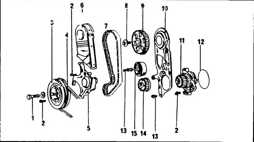
Rice.
203 Timing drive device - 2.4 l engine 1 - bolt, 460 Nm, 2 - bolt, 20 Nm, 3 - vibration damper, 4 - V-belt, 5 - lower toothed belt housing, 6 - upper toothed belt housing, 7 - toothed belt, 8 - bolt, 85 Nm, 9 - camshaft sprocket, 10 - rear toothed belt cover, 11 - coolant pump 12 - O-ring (always replace), 13 - bolt, 10Nm, 14 - crankshaft sprocket, 15 - pulley
The camshaft mounted in the head of the block is driven by a toothed belt worn on the toothed pulleys of the camshaft, crankshaft, coolant pump and a smooth pulley.
The injection pump drive pulley is mounted on the opposite side of the camshaft. The injection pump is also driven by a toothed belt. The injection pump drive is shown in fig. 202. ♦ When changing timing belts, use fig. 203 and 204. Tilt the front panel of the car forward and remove the crankcase protection as described in Chapter 1.

Rice.
204 Injection pump drive device 1 - injection pump drive wheel on the camshaft, 2 - timing belt, 3 - bolt, 100 Nm, 4 - injection pump timing belt cover, 5 - injection pump timing pulley, 6 - nut, 45 Nm, 7 - bolt, 25 Nm , 8 - injection pump, 9 - nut, 25 Nm, 10 - high pressure fuel pipes, 11 - injection pump front bracket
♦ Loosen the alternator mounting bolts, move it towards the block and remove the V-belt.
The belt tensioner in this engine is similar to the tensioner in a gasoline engine. ♦ Remove the top and bottom toothed belt guards.
♦ Loosen the mounting nuts and remove the valve cover.
Loosen the hose connected in the middle and remove. ♦ Turn the crankshaft so that the "0" mark on the flywheel and the pointer in the window of the clutch housing are aligned (TDC of the piston of the first cylinder), and the marks on the injection pump sprocket and on the pump bracket are in line, as shown in fig. 205.
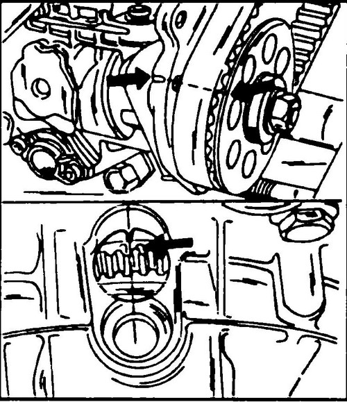
Rice. 205 Installing a mark on the injection pump pulley relative to the mark on the pump bracket (above) and the TDC mark on the flywheel relative to the pointer in the control hole of the clutch housing (below)
♦ Now it is necessary to block the injection pump pulley by inserting a special pin into it, shown in fig. 206. Turn away a bolt of fastening and take out it together with a big washer. Remove the injection pump pulley, as well as the pump timing belt.
Rice. 206 Pin installed in the injection pump pulley (left) and injection pump pulley retainer on the camshaft (right)
♦ Fix the injection pump drive wheel on the camshaft with a tool similar to that shown in fig.
206 and loosen the camshaft bolt. It is only necessary to remove this bolt when the camshaft sprocket needs to be replaced. ♦ Lock the crankshaft (apply the handbrake by engaging first gear) and remove the bolt securing the vibration damper drive pulley.
For locking, a special tool is used (see the description of removing / installing the fuel pump). ♦ Now it is necessary to fix the injection pump pulley by inserting the pin shown in fig.
206. ♦ Remove the injection pump timing belt cover.
♦ While holding the injection pump sprocket with the pin shown in fig.
206, unscrew and remove the mounting bolt together with the large washer. Remove the injection pump pulley, as well as the pump timing belt. ♦ Fix the injection pump drive pulley on the camshaft with a tool similar to that shown in fig.
206, then remove the camshaft bolt. Unscrew this bolt only when the camshaft pulley needs to be replaced. ♦ Block the crankshaft (by applying the handbrake and engaging first gear) and unscrew the bolt securing the crankshaft drive wheel, or rather the vibration damper.
For fixing, you can use a special tool, which will be described below when removing and installing the fuel pump. ♦ Without changing the position of the camshaft, install a setting ruler on the back of the upper surface of the block head, as shown in fig. 207.
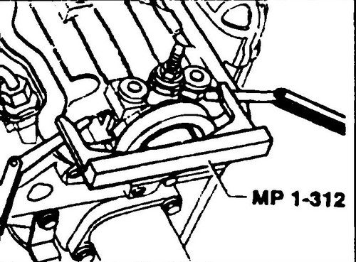
Rice. 207 Locking the camshaft with MP 1-312 before removing the toothed belt
♦ Loosen the coolant pump mounting bolts and turn it so that the timing belt is loose enough.
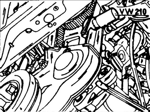
Remove the vibration damper together with the crankshaft timing elbow without moving the crankshaft, and remove the timing belt. ♦ If all parts of the timing drive must be replaced, the intermediate roller must also be removed. Remove it with a puller, after unscrewing the fastening bolt (see Fig. 208).
Rice. 208 Removing the toothed pulley roller with puller 3134/1
If the engine is removed from a Transporter T4 , then after installing a new toothed belt, the valve timing must be adjusted.
If the engine has not been removed from the vehicle, the correct timing is shown in fig. 205. Mount the toothed belt as follows:
♦ Place the toothed belt over the crankshaft toothed pulley at the rear of the vibration damper.
Fit the vibration damper to the crankshaft, making sure that the toothed belt is not wedged between the toothed pulley and the oil pump. ♦ Install the holder in the vibration damper and its arm as shown in fig. 209. If there is no holder, block the crankshaft in another way.
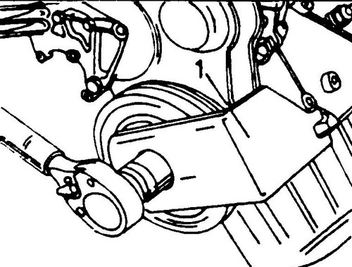
Rice. 209 Fixing the vibration damper with holder 3248 (1)
♦ Coat the bolt with AMW 188 00002 (thread and head bearing surface) and screw it into the crankshaft.
♦ Tighten the bolt to 460 Nm.
♦ If the roller has been removed, reinstall it and tighten the bolt to 10 Nm.
♦ If the camshaft pulley bolt has not been loosened, loosen the camshaft - one turn, the timing pulley is loosened on the camshaft journal as follows: insert the rod into the hole in the rear casing and hit the rod with a hammer.
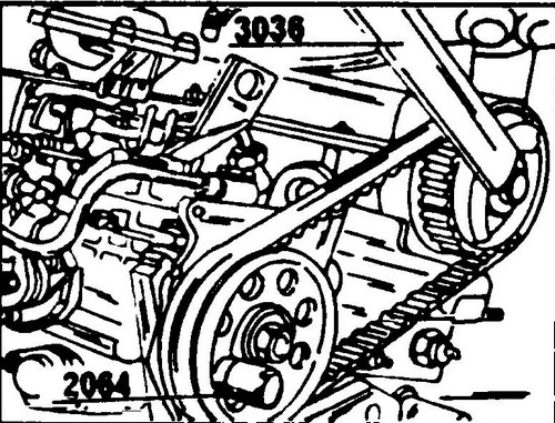
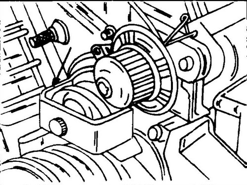
♦ Place the toothed belt on the camshaft pulley and also on the coolant pump pulley and tension it. To tighten the belt, install the tool shown in fig. 210.
Rice. 210 To measure the tension of the toothed belt, install the tool in the position shown
♦ Slightly tighten the coolant pump mounting bolts and turn it in the elongated holes until the tool pointer is between 12 and 13. Tighten the coolant pump mounting bolts to 20 Nm.
♦ Once again check that the engine is set to the TDC position of the first cylinder, and remove the setting bar from the rear end of the camshaft.
♦ Tighten the timing pulley bolt to 85 Nm.
While tightening, block the wheel again. ♦ Fit the high pressure pump pulley with toothed belt onto the camshaft.
Tighten the pulley bolt just enough to allow it to be rotated by hand while tightening. Checking the tension and tension of the toothed belt is described below. ♦ Check again if the TDC setting has changed.
Hold the injection pump drive pulley in the same way as when removing the toothed belt on the camshaft and tighten the bolt to 100 Nm. ♦ Remove the dowel pin from the injection pump pulley.
♦ Rotate the crankshaft, and then install it so that the “0” mark on the flywheel and the pointer in the clutch housing inspection hole are in line.
In this position, check whether the locating pin enters the injection pump pulley hole, and whether the marks on the pump pulley and its bracket are in line (see Fig. 205) If so, then the gas distribution system and the injection pump are installed correctly. ♦ If the crankshaft drive wheel has been removed, tighten its four bolts to 20 Nm.
♦ After installing all parts, check and, if necessary, adjust the compression start of the injection pump.
♦ Fit all timing belt guards and finally adjust the alternator V-belt tension as described below.
Basic technical characteristics T4 . The device and description of the T4 engine .