Engine disassembly
When repairing the engine, remember the following. If, after disassembling the T4 Conveyor engine, you find metal chips or other signs of wear in the cylinder block, in addition to thoroughly cleaning the oil channels, you need to replace all oil jets, a check valve that controls oil return, and an oil cooler, since metal particles sometimes settle in these nodes .
If you want to completely disassemble the Transporter T4 engine , then sequentially perform the individual work steps in the sequence shown.
When disassembling the engine, remember to mark the mounting position of all moving or sliding parts in order to return them to their original position during reassembly. This is especially important for pistons, valves, bearing caps and bearing shells. Details must be laid out so that they cannot be confused. Do not mark the sliding surfaces of bearings and sealing surfaces with a scriber, do not stamp numbers on them. Many parts are made of aluminum and its alloys and must be handled accordingly. In the case of a complete disassembly, it is sufficient to sequentially carry out the individual operations in the sequence below.
♦ Remove all components from the engine: starter, alternator, ignition distributor, intake manifold with carburetor (if any), exhaust manifold, injection system components, etc.
In almost any, even partial disassembly of the engine, it is necessary to remove / replace the V-belts and / or toothed belts.
When characteristic noises appear, it is usually necessary to adjust the tension of the corresponding belt (belts). During these works, follow a few simple rules: - do not hesitate to replace belts that are damaged or soiled with oil / grease.
A broken belt can cause severe engine damage. - timely replace the timing belt, regardless of its condition, for the same reason.
- Try not to overtighten the straps.
Constriction leads to accelerated failure of both the belt and the corresponding bearings. ♦ When dismantling the Transporter T4 engine, remove the timing belt cover, remove the timing belt.
♦ From the front of the engine, remove the toothed belt tensioner.
♦ Loosen the mounting bolt and remove the drive pulley together with the timing gear from the crankshaft.
♦ Remove the coolant pump.
Check the ease of rotation of the water pump shaft. If damaged or leaking, the water pump must be replaced as an assembly. ♦ Remove the oil filter.
If the engine has an oil cooler, which is usually installed between the oil filter bracket and the filter, then unscrew the mounting nuts and remove the radiator. ♦ If necessary, remove the oil filter bracket from the engine.
♦ Remove the dipstick.
♦ Remove the head cover and remove its gasket.
♦ Remove the block head.
♦ Turn the engine over, remove the oil sump and its gasket.
♦ Remove the oil pump.
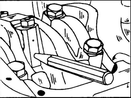
♦ Mark the connecting rod caps with the numbers of the corresponding cylinders (with paint or a punch, as shown in Fig. 70) and remove them one by one. During dismantling, the connecting rod must be at BDC. Remove the pistons together with the connecting rods from the cylinders upwards (towards the head of the block). Connecting rod bolts deform when tightened and must therefore be replaced.
Rice. 70 Marking the connecting rod and its cap before disassembly
♦ Remove the crankshaft main bearing caps.
They are indicated by numbers (No. 1 on the side of the belt pulley, No. 5 on the side of the flywheel - see Fig. 73). ♦ To disassemble the T4 engine, remove the countershaft drive gear.
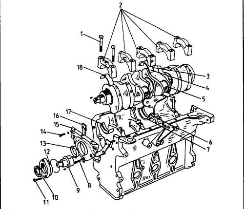
♦ After loosening the fastening bolts, remove the intermediate shaft flange. Remove the shaft from the engine. On fig. 71 shows the device of the lower part of the engine. This drawing must be used during engine disassembly/assembly.
Rice.
71 Location of the crankshaft and intermediate shaft in the cylinder block 1 - main bearing cap bolt, 2 - main bearing cap, 3 - lower support half ring, 4 - main bearing half without oil hole, 5 - crankshaft, 6 - main bearing half with oil hole, 7 - upper support half ring, 8 - bolt, 10 Nm, 9 - intermediate shaft, 10 - oil seal, 11 - bolt, 25 Nm, 12 - intermediate shaft flange, 13 - front crankshaft oil seal, 14 - bolt, 20 Nm, 15 - front flange stuffing box. 16 - gasket, 17 - half liner with oil hole, 18 - half liner without oil hole
Assembling the engine Transporter T4
Engine assembly is carried out in the reverse order to the disassembly of the T4 engine.
Coat all rotating and moving parts with a thin layer of oil.
It is especially important to generously lubricate the surfaces of the pistons, piston rings and cylinder walls with engine oil before assembly. The installation of the vibration damper and the belt pulley on the toothed belt gear is possible only in one position, because
holes are not symmetrical. The threaded surface of the central bolt of the vibration damper and the adjacent surface of the head must be coated with a locking agent during assembly.
Due to the high torque, the vehicle must be on its wheels when the screw is tightened. When unscrewing and tightening, it is recommended to use tool VW-3248-A.
Specifications Volkswagen T4 . Description of the R4 engine .

