Replacing the fluid drive disc (automatic transmission)
The drive disc of the Transporter T4 is fixed to the crankshaft with six bolts with washers. One reinforcing pad is located between the bolt heads and the disk surface (see Fig. 120). This lining is chamfered on one side on the outer perimeter. It is necessary to install the lining so that the chamfer is directed towards the disk.
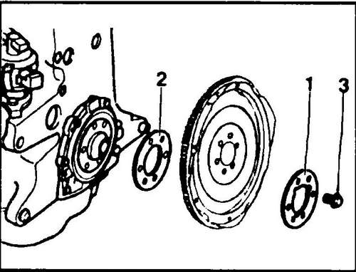
Rice.
120 Hydraulic clutch drive disc 1 - bolt pad, 2 - spacer pad
♦ During installation, coat the bolts holding the drive plate with locking agent and tighten them with a tightening torque of 100 Nm. Do not forget to insert a second washer-lining between the crankshaft and the drive disk, which determines the amount of the axial protrusion of the drive disk. Before you cover the bolts with a tool, install the drive disk and measure the distance from the disk to the body with a depth gauge (Fig. 121).
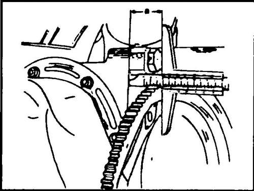
Rice. 121 Measuring the distance from the drive disk to the cylinder block
Support the crossbar of the slider of the measuring device against the drive disk from the side to which the hydraulic coupling is fixed and extend the leg of the depth gauge to the surface of the housing.
This size should be 30.5-32.1 mm. If necessary, purchase and install (remove) pads of appropriate thickness. The new disc only has a “0” mark, and therefore the appropriate mark for adjusting the start of ignition must be applied independently, similarly to that described above for the flywheel.
Volvo S-40 car - volvo-s40-cars.ru . Flywheel Conveyor T4.