Removing the cylinder head VR6
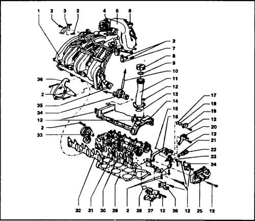
On fig. 142 shows the parts that must be dismantled in order to remove the block head from the cylinder block. If the Transporter T4 is installed in a Volkswagen Transporter T4 vehicle, then a certain amount of work must be done to prepare the engine for dismantling the head of the block.
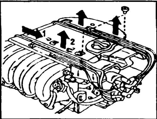
Rice. 141 Removing spark plug high voltage guide wires
Rice.
142 Cylinder head - 6-cylinder engine 1 - intake manifold, 2 - bolt, 25 Nm, 3 - rear right support, 4 - throttle valve assembly, 5 - air duct, 6 - EGR valve, 7 - rear left support, 8 - cover, 9 - gasket, 10 - vacuum hose, 11 - oil filler pipe, 12 - nut, 10 Nm, 13 - ring, 14 - valve cover, 15 - o-ring, 16 - camshaft gear housing, 17 - spacer ring , 18 - O-ring, 19 - Hall sensor, 20 - bracket, 21 - O-ring, 22 - chain tensioner, 23 - ground bus, 24 - bracket, 25 - high voltage transformer, 26 - bracket, 27 - thermostat housing, 28 - o-ring, 29 - cylinder head gasket, 30 - cylinder head, 31 - cylinder head bolt, 32 - lower intake manifold gasket, 33 - poly V-belt tensioner, 34 - crankcase ventilation valve, 35 - connector, 36 - bracket .
♦ Remove the distributor cover, pull out the spark plug wire connectors, remove the high voltage wire guides from the block head.
Slide the guides to the middle and then remove them upwards (see arrow in Fig. 141). ♦ Remove the valve head cover (14).
The valve cover gasket must be replaced. When laying a new gasket, make sure that it is in the correct mounting position. ♦ Remove the upper part of the intake manifold.
The upper part of the collector is attached to the lower part - and to the brackets on the rear wall. Then remove brackets (3, 7). ♦ On the other side of the head, remove the exhaust heat shield, disconnect and remove the manifold from the head.
Remove the manifold gaskets. Pay attention to how both gaskets are installed so that the new ones are installed exactly the same when reassembling. The collector consists of two parts with a fitting for sampling exhaust gases for CO content. ♦ Remove the cover (14) from the block head.
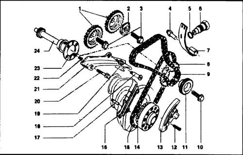
♦ Remove the camshaft drive, detailed in the next section, removing the top chain from both camshaft sprockets (see Fig. 143)
Rice.
143 VR-6 engine chain drive 1 - camshaft sprockets, 2 - sensor disc, 3 - bolt 100 Nm, 4 - axle, 25 Nm, 5 - O-ring, 6 - chain tensioner, 30 Nm, 7 - tensioner bar, 8 ,11 - chain sprocket, 9 - double-row roller chain, 10 - bolt, 100 Nm, 12 - bolt, 10 Nm, 13 - chain tensioner with bar, 14 - drive sprocket, 15 - single-row roller chain, 16 - damper bar, 17 - chamber without shoulder, 25 Nm, 18 - finger with shoulder, 25 Nm, 19,20,22 - bolts, 20 Nm, 21 - damper bar, 23 - adjusting washer, 24 - intermediate shaft
♦ Remove the ignition distributor.
♦ Remove from the head of the block the tensioning devices.0 of the double-row chain (6, see fig. 143).
♦ Unscrew the bracket located under the camshaft cover and then remove the cover (16).
During assembly, this cover must be coated with sealant (AMV 188 001 002). If you removed only the cover, without dismantling the block head, then it is necessary to prepare the sealing surfaces of the cylinder head for assembly, as described below. ♦ Unscrew the block head mounting bolts step by step in the order opposite to that shown in fig. 144.
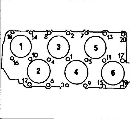
Pic. 144 Head bolt tightening order
♦ Remove the head from the cylinder block.
If the head is “stuck”, remove it with a rubber or plastic hammer, in no case drive a screwdriver along the joint. If you want to further disassemble the cylinder head, you must remove the lower part of the intake manifold, belt tensioner, fuel distributor and other parts mounted on the cylinder head.
The dismantling of the camshafts is described in a separate section.
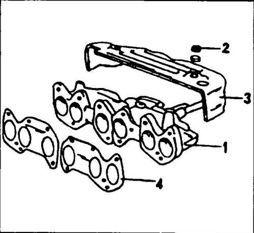
Rice.
145 Exhaust manifold 1 - two-piece exhaust manifold, 2 - nut, 25 Nm, 3 - heat shield, 4 - gasket
Normal oil pressure T4 Conveyor. Description of the VR6 engine .