VR6 cylinder head assembly
The cylinder head of the Volkswagen Transporter T4 is assembled in the reverse order, taking into account the following recommendations.
♦ Coat the valve stems with engine oil and insert the valves into their respective guides.
Please note that after lapping, the valve and seat form a pair, so the valve and guide must be marked. Put oil scraper caps on the rods.
A special tool (3129) must be used for installation. ♦ Install the inner and outer springs on the valve stem, if the parts have not been changed, then they should return to their original places.
♦ Install the upper valve head, use a puller to compress the springs while holding the valve as shown in fig.
151. When the valve stem protrudes from the upper spring cup to a sufficient height, install the valve cotters into the groove of the stem and slowly release the puller. ♦ Tap the end of the valve stem that is covered with a rag with a plastic mallet.
Incorrectly installed crackers will pop out. Rags will not allow crackers to get lost. ♦ In accordance with the previously made marks, install pushers in the holes of the head of the block, having previously lubricated them with engine oil.
♦ When assembling the cylinder head, liberally lubricate the camshaft bearing journals with engine oil.
♦ Install the camshafts in the bed of the head.
Finally, turn the shafts so that both valve cams of the first cylinder point upwards. Installation of camshafts on the block head is described on the next page.
Camshaft of cylinders 1, 3 and 5
♦ Lubricate the inside of the bearing caps generously and install caps 3 and 5 respectively (see Fig. 149) on the camshaft.
Now let's check if the installation is correct. The numbers should be read from the exhaust manifold side and the arrows on the covers should point towards the crankshaft pulley. ♦ Alternately and crosswise tighten the four nuts in several stages, tightening torque 20 Nm.
With uniform tightening, the valve springs are compressed slowly and the camshaft does not warp. ♦ Install covers 1 and 7 and check again for correct installation.
♦ Tighten the nuts of both covers crosswise, tightening torque 20 Nm.
♦ Rotate the camshaft several times to make sure it turns without problems.
Camshaft of cylinders 2, 4 and 6
♦ Lubricate the inside of caps 2 and 6 liberally with engine oil and install (see Fig. 149) on the camshaft.
Now check if the installation is correct. The numbers should be read from the exhaust manifold side and the arrows on the covers should point towards the crankshaft pulley. ♦ When assembling the Volkswagen T4 cylinder head alternately and crosswise in several passes, tighten the four nuts, tightening torque 20 Nm.
With uniform tightening, the valve springs are compressed slowly and the camshaft does not warp. ♦ Replace cover 4 and check again for correct installation.
♦ Tighten the bearing cap nuts crosswise, tightening torque 20 Nm.
♦ Rotate the camshaft several times to make sure it turns without problems.
♦ Install sprockets on both shafts.
Try not to confuse the stars in places. ♦ Tighten the fastening bolts.
There is a hexagon on the camshaft (see fig. 147), for which the shaft can be easily held with a 24 mm open-end wrench, tighten both bolts, tightening torque 100 Nm. For one of the shafts, place the ignition distributor drive gear. ♦ Thoroughly clean the sealing surface of the block under the drive sprocket cover.
♦ Thoroughly clean the seating surface of the cover and coat it with sealant AMV 188 00202.
♦ Attach the cover. First tighten the bolts by hand, then finally tighten them around the perimeter to a torque of 10 Nm. On the inside of the cover there is an O-ring which must remain in place. If both or only one camshaft is removed without removing the engine from the vehicle, thoroughly clean both 3 mm holes in the valve cover (see Fig. 159), and coat them with sealant before installing the valve cover. Install the ignition distributor.
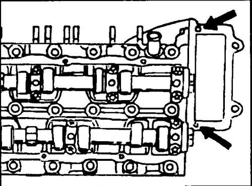
Rice. 159 3 mm - holes on the valve cover
♦ Install all previously removed parts on the block head in the reverse order, note that some of the parts are mounted when assembling the block head.