Removal and installation of the diesel engine
The 1.9L engine is removed in the same way as the petrol engine.
The engine goes down without the gearbox. The 2.4 liter engine is removed along with the gearbox. Given these differences, both engines will be described separately. Four-cylinder engine
After tilting the front panel and the radiator, the following operations must be performed:
♦ Disconnect the “gas” rods from the high-pressure fuel pump.
Remove the latch of the thrust sheath on the bracket, disconnect the sheath. ♦ Disconnect both fuel lines from the injection pump.
♦ Disconnect the cold starter link. Lock the rod and screw in the adjusting bolt (see 1, fig. 181). Separate the halves (2) and (3) and remove the rod from the connector.
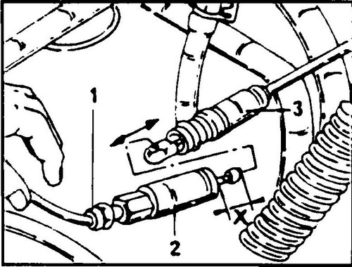
Rice. 181 Disconnecting the cold starter rod
The engine is installed in the reverse order.
Five-cylinder engine
♦ Disconnect the battery.
♦ Remove the engine cover and tilt the front of the car forward.
♦ Remove the heatsink.
♦ Disconnect the throttle link from the injection pump lever.
Disconnect draft of the device of start of the cold engine as it has been described above for the four-cylinder engine (see fig. 182). ♦ Loosen the knurled nut and remove the speedometer drive shaft.
♦ Disconnect the linkage from the clutch release lever or remove the clutch slave cylinder without disengaging the hydraulic actuator.
♦ Disconnect all electrical wires from the engine, gearbox and starter.
♦ Disconnect the shift mechanism from the gearbox.
♦ Disconnect the fork head connection 1 (see fig. 182).
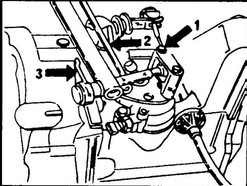
Rice. 182 Detaching gearshift mechanism
♦ At the front of the shift lever, remove the lever (2) from the hinge.
♦ Remove the arm with lever (3).
♦ Disconnect the oil lines from the power steering pump and collect the escaping oil in a prepared container.
♦ Remove the left and right axle shafts.
♦ Disconnect the front exhaust pipe from the exhaust manifold.
♦ Disconnect the high pressure pipe and return pipe from the power steering pump and carefully place them aside.
♦ Loosen the four bolts (see arrow in fig. 183) to loosen the gearbox mount.

Rice. Fig. 183 Mounting points (see arrow) of the support of the solo unit at the gearbox - engine 2.4 l
♦ Place a jack under the power unit by placing a wooden block under the heel of the jack, and lift the power unit to unload its suspension mounts of the Volkswagen Transporter T4 .
♦ In the engine compartment, unscrew the central bolts of the engine and gearbox mounts on the left and right sides.
♦ Jack down the engine together with the gearbox.
When doing this, pay attention to the fact that the electrical wires or body hoses do not catch on the engine or gearbox. A second person must support the power unit on the lift until it is completely removed from the vehicle. ♦ After removing the power unit, remove the starter and disconnect the gearbox from the engine.
During the separation of the engine and gearbox, the gearbox must not be allowed to hang on the input shaft in the clutch disc. The gearbox must be supported and moved so that the input shaft is always in the axis of the crankshaft. ♦ Install the engine in reverse order.
Bolt tightening torques:
Engine to gearbox
M12 bolts 80 Nm
M 10 bolts 60 Nm
M8 bolts 20 Nm
Transmission support crossbar
M 10x60
bolts 65 Nm M 10x28 bolts 45 Nm
Engine/gearbox mounting 65 Nm
Articulated axle shaft flanges 55 Nm
Connecting fuel pipes , it must be remembered that the drain pipe has a smaller diameter and the inscription “OUT” is placed on the hexagonal head of its union nut. These tubes cannot be interchanged.