Stabilizer - removal and installation
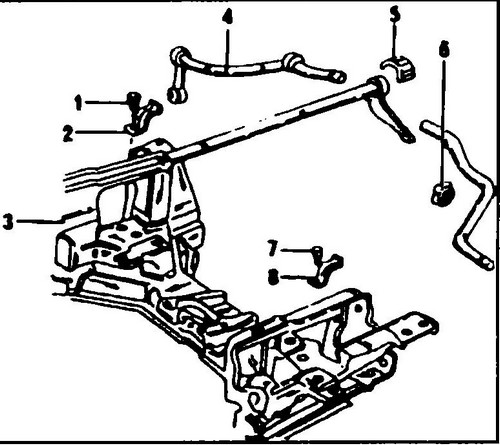
On fig. 393 shows the attachment of the stabilizer Transporter T4 to the front suspension beam.
Rice.
393 T4 stabilizer attachment points 1 - bolt, 55 Nm, 2, 8 - clips, 3 - front suspension beam, 4 - stabilizer bar, 5 - rubber pad, 6 - nut, 7 - bolt, 55 Nm
Stabilizer Conveyor T4 is fixed to the beam with rubber bushings and clips.
Both ends of the stabilizer are attached to the lower wishbones with supports. The long bolt that secures the support also serves to mount the shock absorber. This connection is shown in detail in Fig. 389. The stabilizer is removed in the following way: ♦ Fit the load-bearing supports in the front suspension.
♦ On both sides of the vehicle, disconnect the lower shock absorber mounts and knock out the long bolts.
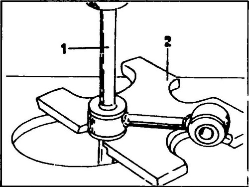
The supports are removed together with the stabilizer, as they are pressed onto it. ♦ Unscrew the bolts (1 and 7, fig. 394), remove the clips (2) and (8), remove the stabilizer from the vehicle.
Rice. 394 Removing the stabilizer from the support
To detach the stabilizer, it is necessary to install it on a press, as shown in fig.
395 and press the stabilizer bar with the support. The stabilizer Transporter T4 also has rubber bushings. If these bushings are worn, the bearing assemblies must be replaced. The stabilizer is installed in the reverse order. The tightening torques must be taken from fig. 390 and 394. The specified tightening torques must be strictly adhered to during assembly.
Rice.
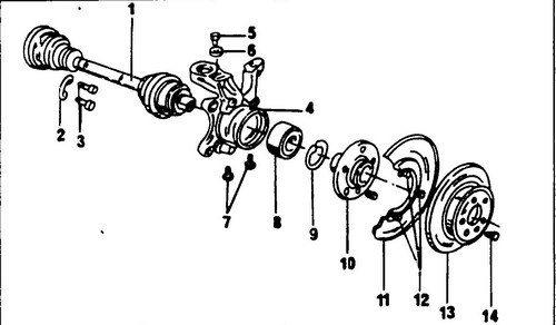
395 Steering knuckle and wheel hub device 1 - drive shaft, 2 - folding washer, 3 - bolt, 55 Nm, 4 - steering knuckle, 5 - bolt, 60 Nm, 6 - washer, 7 - bolt, 77 Nm (attaches the lower ball joint hinge to the steering knuckle), 8 - wheel bearing, 9 - retaining spring ring, 10 - wheel hub, 11 - tin casing, 12 - bolt, 8Nm, 13 - brake disc, 14 - bolt, 5Nm


