Removing the steering gear
A hydraulic cylinder is used as an actuating unit of the hydraulic booster. It is fixed on one side of the steering gear, and its piston is connected to the steering gear rack. Depending on the direction of the steering wheel movement, pressurized hydraulic fluid is supplied from one side or the other of the piston, which significantly reduces the effort on the steering wheel required to steer the car. The power steering system uses the same hydraulic fluid as automatic transmissions. The system has its own compensation tank. During removal, use fig. 410 and follow the instructions below. Cleanliness must be observed when working on the hydraulic systems of the Transporter T4
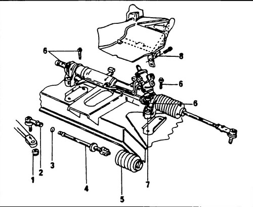
Rice.
410 Power steering bolts 1 - self-locking nut, 40 Nm, 2 - tie rod end, 3 - lock nut, 55 Nm, 4 - tie rod, 5 - toothed bar cover, 6 - steering gear mounting bolt, 7 - steering gear , 8 - thermal protection cover (if any)
♦ Remove the crankcase protection.
♦ Disconnect the front exhaust pipe from the exhaust manifold, remove the pipe from the vehicle.
In early models, a heat shield was installed above the steering gear.
It must be removed first. In cars manufactured later, this casing was not installed. ♦ Loosen the front wheel nuts.
♦ Raise and place the front of the vehicle on stands.
♦ Remove the hollow bolt from the hydraulic booster pump (see arrow fig. 411) and disconnect the hydraulic pipe. Collect escaping hydraulic fluid in a clean container. In a five-cylinder diesel engine, both pipes, that is, return and supply, must be disconnected from the power steering pump.
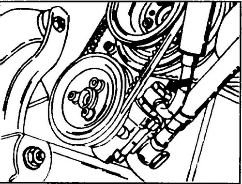
Rice. 411 Hollow bolt (see arrow) securing the hydraulic tube of the power steering pump - engine 2.0
♦ On 1.9 and 2.0 engines: disconnect the hydraulic hoses from the steering gear, wrap the ends of the hoses with a piece of polyethylene film, and then secure the polyethylene with adhesive tape.
This will protect the tubes and hoses from dust ingress. The steering gear connection hole must also be closed. ♦ On the left and right side, unscrew the self-locking nuts securing the steering pins to the steering knuckles. Using an appropriate puller, push the hinge pins out of the steering knuckle arm (see Fig. 412.).
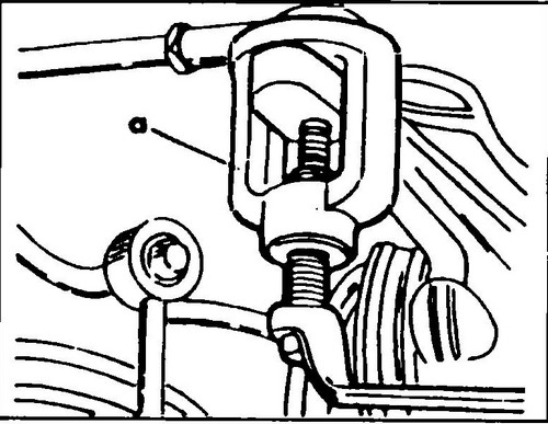
Rice. 412 Detaching the steering joint from the knuckle arm
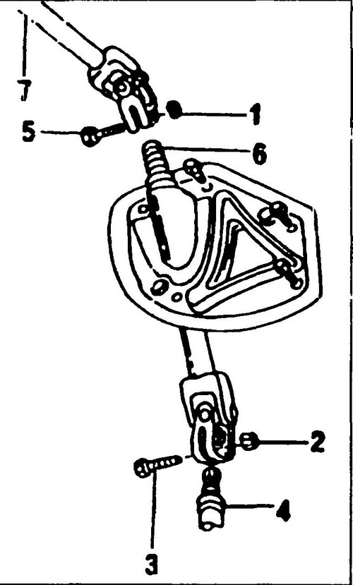
Rice.
413 Fastening the intermediate shaft to the steering gear shaft 1,2 - self-locking nut, 30 Nm, 3, 5 - universal joint bolts, 4 - drive gear shaft, 6 - lower part of the steering shaft, 7 - middle part of the steering shaft
♦ From the bottom of the vehicle, detach and remove the stabilizer mounts on both sides.
The method of connecting the intermediate shaft to the steering gear shaft is shown in fig. 414. ♦ Loosen the bolt (25)/nut (24) securing the intermediate shaft lower universal joint (27) to the pinion shaft.
♦ On the left and right side, remove the steering gear mounting bolts.
♦ Raise the stabilizer bar up and secure it in this position.
♦ Move the steering gear slightly to the right so that the end of the pinion shaft can come out of the universal joint. Lower the left side of the steering gear down and remove it from the chassis.
If a new steering gear is to be installed, it is necessary to disconnect the steering rods from the old transmission.
The detachment method is described below. Installation of the steering mechanism
The steering mechanism is established upside-down.
Fasteners pos (7), (23), (24), (25), (28) (see fig. 414) must be replaced at each disassembly. If the tie rod joints have been removed, they must be reinstalled. Bolts securing the steering gear, tighten to 33 Nm.
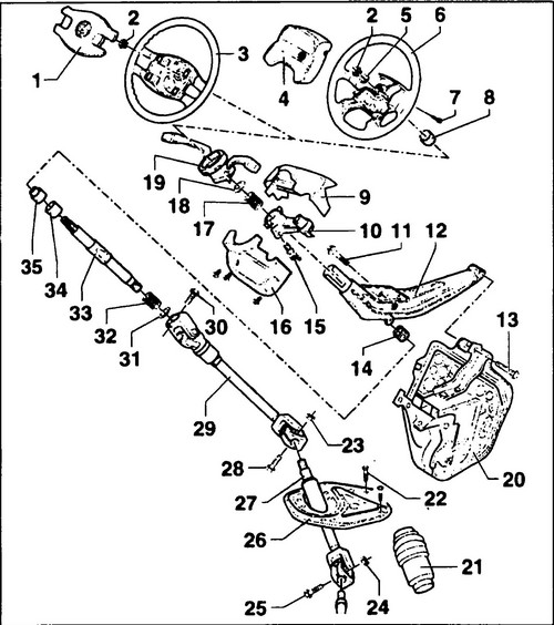
Rice.
414 Steering column device 1 - cover, 2 - steering shaft nut, 70 Nm, 3 - steering wheel (without pillow), 4 - airbag, 5 - washer, 6 - steering wheel with airbag, 7 - Torx bolt ", 6.5 Nm, 8 - bushing, 9 - upper decorative panel, 10 - steering shaft lock housing, 11 - bolt, 50 Nm, 12 - steering column tube-bracket, 13 - bolt, 25 Nm, 14 - steering shaft bearing, 15 - shear bolt, 16 - lower decorative panel, 17 - spring, 18 - lock washer, 19 - horn contact group, 20 - body support bracket, 21 - housing - cover, 22 - bolt, 20Nm, 23, 24 - self-locking nuts , 30 Nm + 90º, 25, 28 - bolts, 26 - bracket with guide sleeve, 27 - lower intermediate steering shaft, 29 - upper intermediate steering shaft, 30 - bolt, 30 Nm, + 2 times 45º, 31 - washer, 32 - lower spring, 33 - steering shaft, 34 - support ring, 35 - adapter
♦ Insert the ball stud of the tie rod end into the bore of the steering knuckle arm, screw in a new self-locking nut and tighten it to 40 Nm, tighten the tie rod lock nuts after adjusting the camber/toe to 55 Nm. After connecting the hydraulic pipes and hoses, fill the hydraulic system with fluid and bleed it.