Brake pads - replacement
Since the disc brakes on the 14" and 15" Transporter T4 are different, the procedure
for replacing the T4 brake pads in both cases will be described separately.
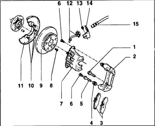
In any disc brake mechanisms, the pads are changed as a set on the axle (four pieces). Lucas brakes were installed in 14 "wheels (see Fig. 424).
Rice.
424. Lucas floating brake device 1 - bolt, 280 Nm, 2 - caliper, 3 - brake pads, 4 - rubber cap, 5 - guide rod, 6 - bolt, 35 Nm, 7 - caliper, 8 - type bolt Torx, 10 Nm, 9 - brake disc, 10, 13 - bolts, 10 Nm, 11 - brake shield, 12 - brake pipe, 14 - brake hose bracket, 15 - brake hose
Self-locking bolts with separate guide rods are used to fasten the brake caliper housing.
To measure the thickness of the brake pads, remove the front wheel from the driver's side.
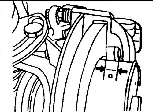
In the appropriate place (see. Fig. 425) measure the thickness of the pads with a caliper. If the brake pad (lining plus metal plate) is less than 7 mm thick, then all pads on that axle must be replaced. The brake pads are replaced as follows:
♦ Raise the front of the vehicle and install stands.
♦ Loosen the screw (6) (see fig. 424) with a spanner while holding the guide rod (5).
Rice. 425 Measuring the thickness of the brake pads Conveyor T4
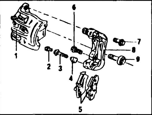
Rice.
426 Wheel brake caliper 14" 1 - caliper body, 2 - self-locking bolt, 35 Nm, 3 - guide rod, 4 - rubber boot, 5 - set of brake pads, 6 - bolt, 270 Nm, 7 - bolt, 160 Nm, 8 - caliper housing, 9 - drive axle bolt, 200 Nm
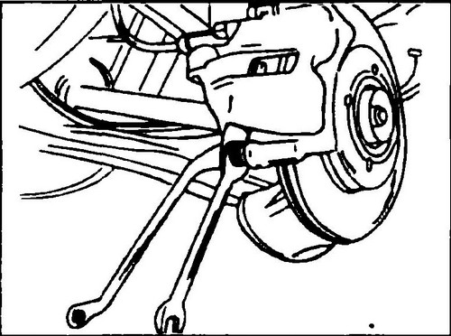
Rice.
427 Loose lower caliper housing bolt. Hold the hexagon of the guide rod with an open end wrench.
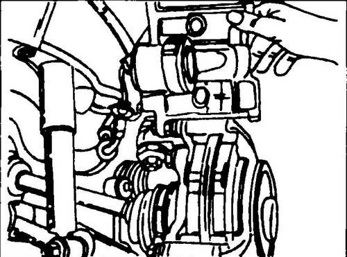
♦ Tilt the caliper body up (fig. 428). Now both Volkswagen T4 brake pads are accessible and can be removed.
Rice. 428 Removing the brake pads from the caliper housing
♦ Use a hardwood wedge to carefully push the piston into the cylinder.
Since this will cause the brake fluid level in the reservoir on the master cylinder to rise, some of the fluid can be removed beforehand. Now access to the frame and caliper body is open.
Check for signs of brake fluid leaks indicating a leak in the caliper housing. If traces of brake fluid are evident, the caliper cylinder must be repaired or replaced. T4 brake pads are installed in the following way:
♦ Install both brake pads in the caliper frame with the friction lining facing the brake disc.
If the brake pads cannot be installed in the caliper housing, then the reason for this may be insufficient recession of the piston in the cylinder bore. You can drown the piston with a special tool. It is installed in the brake caliper housing (see Fig. 431). By rotating the central bolt of the fixture, the piston moves into the cylinder. ♦ Carefully lower the caliper body onto the supports and screw in the fixing bolt.
This is a self-locking bolt and must be replaced after each unscrewing. ♦ Hold the guide rod as shown in fig.
427 and tighten the mounting bolt to 35 Nm. ♦ Perform all other work in reverse order.
If necessary, add brake fluid to the expansion tank. ♦ Depress the brake pedal several times to bring the brake pads to working condition.
Remember, during the running-in period of the pads, the effectiveness of the brakes is reduced. ♦ Tighten the wheel nuts to 110 Nm.
On 15" wheels
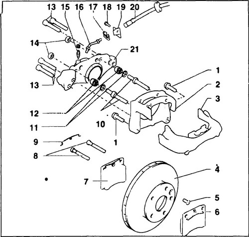
Fits a Lucas frame mechanism (see fig. 429)
Rice.
429 Lucas frame mechanism - models with 15" wheels 1 - bolt, 280Nm, 2 - bracket, 3 - caliper, 4 - brake disc, 5 - Torx bolt, 10Nm, 6, 7 - T4 brake pads, 8 - pad guide pins, 9 - spring clip, 10 - guides, 11 - rings, 12 - rubber cap, 13 - Torx bolt, 90Nm, 11 - brake shield, 12 - brake pipe, 14 - nut, 70Nm, 15 - bleeder valve, 16 - brake pipe, 17 - retaining clip, 18 - bolt, 10Nm, 19 - brake hose bracket, 20 - brake hose, 21 - caliper body
In this version, the brake pads are mounted on guides, so there is no need to detach the brake caliper to replace the brake pads.
The thickness of the brake pads is checked in the same way as for the 14" wheel caliper. Fig. 9.4 is also valid for this version. The brake pads are removed as follows: ♦ Loosen the nuts of both wheels, raise
the front of the car and place stands, remove both wheels.
♦ On both sides remove the locking spring (9, fig. 429)
♦ Retract the pin and drive out both stop pins in turn from outside to inside
♦ Remove the brake pads (3) If they are sticky, insert a bent wire into the holes from the locking pins and jerk off
♦ Drive the piston into the caliper body cylinder using a hardwood wedge as described for wheels 14. If you have the appropriate tool, use it.In this case it is also recommended to remove some brake fluid from the
reservoir . brake pads in the caliper Do not use solvents or sharp-edged tools Check the position and condition of the piston boot.
Damaged, twisted or hardened boots must be replaced. Brake pads are installed in reverse order.
Place both T4 brake pads into the caliper sockets with the holes in the caliper “ears” using a thin rod.
Hammer (from the inside out) the locking pins and put on the locking springs. Perform all other work in reverse order.
♦ Depress the brake pedal until the brake pads are in working position.
Remember, during the running-in period of the pads, the effectiveness of the brakes is reduced.
Tighten the wheel nuts to 110 Nm.
