Checking and replacing the rear brake pads
the Transporter T4 brake pads . On fig. 439 shows the position of the control hole. Light the brake pads through this hole and visually determine the thickness of the pads. If it is less than 1.0 mm or close to this value, replace the pads as a set, that is, on both rear wheels.
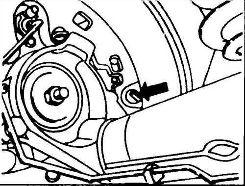
Rice. 439 After removing the plug (see arrow), you can determine the thickness of the friction linings of the brake pads
♦ Raise the rear of the vehicle and place on stands.
♦ Loosen the brake pad self-adjuster, otherwise the drum may hang on the pads and cannot be removed. To do this, insert a screwdriver into the hole shown in fig. 440 and locate behind the brake shield (5) (see fig. 441) the governor gear (16).
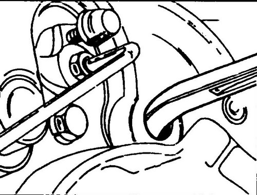
Rice. 440 Adjuster gear can be turned with a screwdriver

Rice.
441 Rear wheel drum brake 1 - bolt, 160 Nm, 2, 23 - Torx screws, 3 - brake drum, 4 - brake shoe guide plates, 5 - guide spring, 6, 10 - lower return springs, 7 - spring bracket, 8 - bracket, 9 - upper return spring, 10 - brake shoe with friction lining, 11 - hand brake lever, 12 - bar - spacer, 13 - bracket return spring, 14 - shoe guide, 15 - brake tube, 16 - bolt, 20Nm, 17 - brake slave cylinder, 18, 19 - bolts, 7Nm, 20 - handbrake cable bracket, 22 -handbrake cable, 24 - brake shield, 25 - pressure regulator spring, 26 - nut, 20Nm, 27 - bolt, 28 - stop bracket, 29 - bushing, 30 - suspension arm, 31 - bolt, 10Nm, 32 - ABS wheel sensor
By turning the wheel in the appropriate direction, move the brake pads.
If during a turn in one direction the pads block the brake drum, then in order to retract them, it is necessary to turn the wheel in the opposite direction.
On the other side of the car, move the blocks in the same way. During the next steps, use Fig.
441 and perform the following operations: From the rear side of the brake shield, press the pad guide with your finger, and from the front, grab the guide plate with tongs. Push the plate down, rotate and detach from the guide. Remove the guide plate and spring. On fig. 442 shows how to grip the guide plate with tongs. It is necessary to remove the guides of both brake pads.
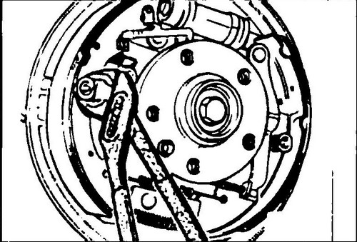
Rice. 442 Turn plate guide brake pads
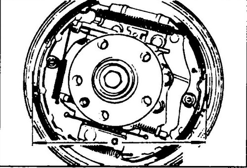
♦ Disconnect the spring (1) on one side (see fig. 443), you can also disconnect the bracket spring (2).
♦ Using a screwdriver, turn the adjuster gear as far as it will go so that the brake pads move as far as possible and disconnect the spring (4) (see Fig. 443).

Rice. 443 Rear wheel brake
♦ Align the brake pads by moving them back and forth.
♦ Use a vernier caliper to measure the diameter of the installed pads (dimension "a" in Fig. 444).
Rice. 444 Installing pads - rear drum brakes
♦ If it is larger than 286 mm, adjust this size by turning the gear wheel.
It is recommended to install the pads so that their diameter is 1 mm smaller than the inner diameter of the brake drum. ♦ Adjust the parking brake as described in section 9.1.
Perform all other work in reverse order. ♦ When the vehicle is back on the ground, depress the brake pedal several times to bring the brake pads into position.
♦ Grab the brake shoe from below as shown in fig. 445 and remove it from the bottom bracket. Disconnect the now loosened lower return spring.

Rice. 445 Removing the brake pads
♦ Tilt the brake shoe down and disconnect the parking brake cable from the release lever. The cable is fixed on the lever with a spring (see Fig. 446). During installation of the cable, the spring must also be stretched. Particular attention should be paid to the pad adjuster. It must be disassembled, cleaned and lubricated. Its left side has a right-hand thread, and the right side has a left-hand thread. The regulator forks are not symmetrical on one side. During assembly, it is necessary to install the regulator so that the long end of the forks is on the side of the brake shield.

Rice. 446 Place of fastening of the parking brake cable
Brake pads are installed in reverse order.
Lightly lubricate the seating surfaces of the brake pads to the brake shield, the lower ends of the pads deposited in the bracket, as well as the hinge of the expanding lever with graphite grease. First, connect the parking brake cable (see Fig. 446), that is, move the spring with pliers as far as possible, settle the tip of the cable in the expanding lever and release the spring so that it fixes the tip in the lever. Check if the cable is securely locked. Install the return springs on the brake shoes. ♦ Insert one shoe first in the shoe bracket.
Pulling on the other block, stretch the return springs and upset the second block (Fig. 445). Reinstall all springs shown in fig. 443. In this case, you can use tongs or a screwdriver. Install the brake shoe guides in reverse order. Push the guide from behind with your finger, put the spring and guide plate on the front, and then push and turn the plate so that it locks on the guide. After installing the pads, it is necessary to adjust the main position of the self-adjuster. We recommend that you proceed as follows: ♦ Fully release the parking brake.
♦ Under the vehicle, loosen the lock nut and unscrew the adjusting nut to loosen the parking brake link at the point shown by the arrow in fig. 422.