Installing the gearbox
Installing the gearbox Transporter T4 is carried out in the reverse order.
In doing so, the following recommendations must be adhered to. ♦ Before installing the gearbox, check the condition of the clutch.
If necessary, repair it as described above. ♦ Check the free play and condition of the release bearing.
If, before dismantling the transmission, when depressing the clutch, characteristic noises were heard in the bearing, the bearing must be replaced. ♦ Clean the gearbox input shaft splines and lubricate them with a thin coat of molybdenum disulphite grease ("Molycot").
If the gearbox is replaced, the shift levers will need to be adjusted after installation.
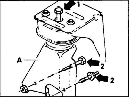
♦ Disconnect the bearing bracket (A, fig. 340) of the gearbox from the rubber-metal support on the body (1), then from the gearbox (2).
Rice. 340 Left support of the power unit
♦ Before installing the gearbox, press the clutch release lever against the gearbox housing and secure it with a special pin or M8x22 screw.
♦ For vehicles with power steering, before installing the gearbox, install the screws securing the clutch housing to the gearbox in the holes in the clutch housing.
♦ Raise the gearbox to the level of the crankshaft and horizontally insert the input shaft and the clutch disc, if installation is difficult, turn the shaft by turning the half shaft mounting flange by hand.
♦ Fasten the screws securing the engine to the gearbox by screwing them in as far as possible.
♦ Rock the power package assembly into place.
At the same time, check the possibility of connecting the right axle shaft to the gearbox shaft flange. To install the bolt of fastening the left support of the power unit to the body, it is necessary to combine the mounting holes of the engine support and gearbox (see Fig. 340).
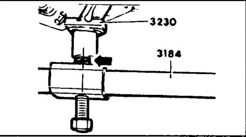
Remove the VW 3184 tool after the final tightening of the support mounting bolts. ♦ Connect the front exhaust pipe with resonator or catalytic converter.
♦ Push the stabilizer in both tie rods all the way up to make room for the exhaust pipe.
♦ Tighten the bearing bracket bolts on the gearbox and on the rubber/metal bearing to 65 Nm.
♦ Install and connect previously removed electrical wires and piping.
♦ Remove tool VW 3184.
♦ Disconnect engine mount VW 3230.
♦ Connect speedometer cable to clutch housing at right axle shaft.
4-cylinder engine: attach the exhaust/fuel tank guard. Models of release before August, 1992: establish a back support of the power unit without stresses in support (see fig. 344 and 368).
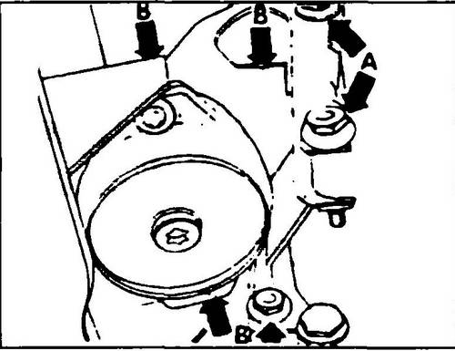
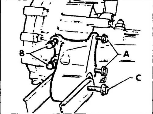
Screws (A, fig. 340) tighten to 65 Nm (if the support was dismantled), screws (B) tighten to 45 Nm. Since August 1992, another rear gearbox support has been installed (see Fig. 345, 367, 369): Bolts (A, Fig. 341) have been increased from 10 mm to 12 mm. The old bolts M 10 for fastening the box support on the bracket of mounted units were replaced with bolts M16 (C). A new rear box support cannot be installed in old machines.
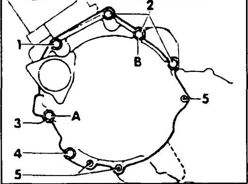
Rice.
341 Gearbox mounting scheme - 4-cylinder engine 1 - M12x130 screw, 80 Nm, 2 - M12x60 screws, 80 Nm, 3 - M12x100 screw, 80 Nm, 5 - M8x32 screw, 25 Nm, 6 - M8x12 screw, 25 Nm, A and B guide bushings
Rice. 342 Leveling the power unit to install the support bolts
Rice.
343 Gearbox mounting scheme - 5-cylinder diesel engine 1 - screw M12x60, 80 Nm, 2 - screws N112x70, 80 Nm, 3 - screw M12x100, 80 Nm, 4 - screw M12x 130, 80 Nm, 5 - screws M8x45, 25 Nm, A and B - guide bushings
Rice. 344 Installation of the rear support - models produced before August 1992
Models since August 1992: Install the power unit rear support without tension. Bolts (A, Fig. 345) tighten to 100 Nm, screws (B) to 40 Nm, screw (C) to 270 Nm.
Rice. 345 Installing the rear powertrain support - models after August 1992
Models with air conditioning: Install the air conditioning compressor.
4-cylinder engine: Reinstall the lower clutch housing cover. Screw in the engine-to-box mounting bolts located above the clutch housing. Tightening torques: M8 bolts - 25 Nm; M12 - 80 Nm.
Rice.
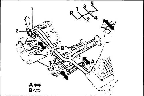
346 Gear shift actuator 1 - Gear shift lever, 2 - gear selector lever hinge A - shift rod, B - gear select lever
Rice.
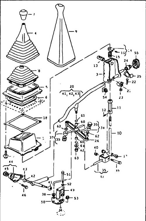
347 Gearbox control mechanism - manual transmission 1 - housing, 2 - screw, 10 Nm, 3 - boot, 4 - corrugated boot, 5 - frame, 6 - frame gasket, 7 - handle, 8 - boot, 9 - boot, 10 - shift lever, 11 - guide sleeve, 12 - locking pin, 13 - support pin, 14 - stop, 15 - compression spring, 16 - threaded pin, 17 - support sleeve, 18 - body gasket, 19 -, 20 - thrust in assembly, 21 - clamp, 22 - screw, 23 - nut, 24 - bushing, 25 - bushing bushing, 26 - rocker arm, 34 - selector lever hinge, 35 - hinge bushing, 37 - reverse gear engagement rod, 38 - bushing, 39 - axle bolt, 40 - M6 self-locking nut, 41, 42 - ball joint, 43 - pin, 44 - bracket, 45 - bushing, 46 - screw, 49 - support, 50 - shift lever, 51 - M6x62 bolt, 53, 63 - M8 nuts, 60 - bushing, 61 - sealing ring, 62 - sealing gasket
♦ Remove the access pin or M8x22 screw from the transmission hole and plug the hole.
♦ Install and adjust the gearshift mechanism.
♦ Attach the wiring harnesses to the coolant hoses.
♦ Connect, according to the markings made before disassembly, the transmission and starter harnesses and connectors.
♦ Replace the heatsink.
♦ Guide the clutch cable into the guide bracket.
♦ Connect the connectors to the battery.
Diesel engine: Fit the brake booster hose to the vacuum pump. ♦ Connect the ground bar to the gearbox.
♦ Reinstall the starter.
♦ Tighten the screw securing the shock absorber to the right stabilizer connecting rod to 160 Nm.
♦ Attach the right axle shaft to the gearbox.
♦ Install the left axle shaft.
♦ Remove tool VW 3250.
♦ 4-cylinder diesel engine: install and adjust injection pump drive cables.
♦ Petrol engine: Connect the brake booster hose to the engine.
♦ Tighten the top screws securing the power unit.
Tightening torques: M8 screw - 25Nm; screw M12 - 80Nm. ♦ Attach wiring harnesses to piping.
♦ Attach the coolant line from the expansion tank to the water pump to the starter.
♦ Install the speedometer cable bracket to the gearbox
On models with a mechanical clutch, attach the clutch cable to the gearbox and bearing bracket.
Fully depress the clutch pedal at least 5 times, then check the operation of the adjusting device as described below.
On models with a hydraulic clutch, attach the slave cylinder to the gearbox, tightening torque of the fasteners is 25 Nm.
♦ Coat the splined surfaces of the drive shafts with graphite powder (graphite grease).
♦ Fasten all gearbox and engine supports without distortion or tension.
♦ On vehicles with a mechanical clutch, fully depress the clutch pedal at least five times.
Tilt the release lever 10 mm in the opposite direction to the movement during release and check the smooth movement of the lever. On vehicles with hydraulic clutch release, bleed the hydraulic system if the system lines were previously disconnected.
♦ Adjust the external gearbox control.
♦ Before reinstalling the gearbox, check that the intermediate plate is correctly installed. Put the box on the guide bushings.
The following tightening torques must be adhered to during assembly:
M8 bolts .............................................. ......20 Nm
Transmission cross member
bolts M 10x60 .................................. ..65 Nm
bolts M10x28......................................45 Nm
Engine/gearbox suspension
gears ............................................... 65 Nm
drive shaft flanges ..............55 Nm
