Removal and installation of the fuel pump and fuel level sensor
The fuel pump of gasoline engines is combined with the fuel level sensor and is located in the fuel tank of the T4 Transporter . In a diesel engine, the fuel pump is built into the injection pump, the fuel level sensor is located on top of the fuel tank (see Fig. 253).
Rice.
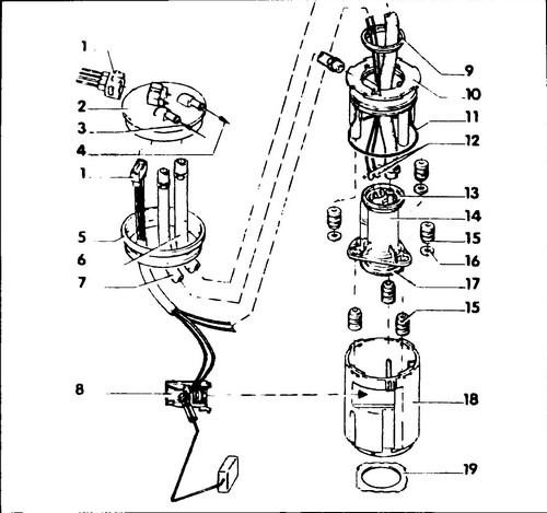
253 Fuel pump and fuel level sensor 1 - wiring connector, 2 - cover, 3 - return of excess fuel from the fuel distributor, 4 - fuel supply (to the fuel filter), 5, 11 - o-rings, 6, 7 - fuel supply hoses, 8 - fuel level sensor, 9 - upper retaining ring, 10 - upper housing, 12 - fuel pump connector, 13 - upper sealing ring, 14 - fuel pump, with strainer and check valve, 15 - support rubber bushing, 16 - washer, 17 - lower o-ring, 18 - lower housing, 19 - ring
Float type fuel level sensor.
When the fuel level drops, the float with the lever drops.
Linked to the potentiometer, the float arm changes the resistance of the sensor. As a result, the voltage on the fuel level indicator on the instrument scale deviates. Removal
♦ Remove the terminals from the battery.
♦ Cut the floor covering to the right of the handbrake lever.
♦ Remove the fuel gauge/fuel pump guard.
♦ Disconnect the level sensor/fuel pump connector by prying up the side retaining tabs with a small screwdriver (see fig. 254).
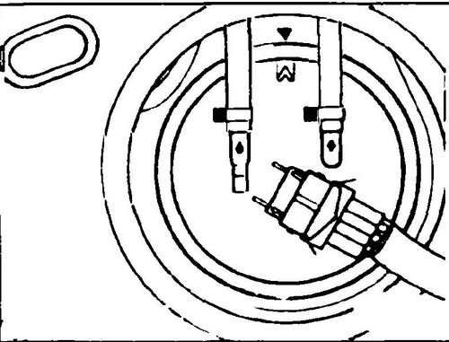
Rice. 254 Disconnect fuel level sensor connector
♦ Loosen the clamps and disconnect the fuel supply and return lines from the hoses.
♦ Loosen the union nut with the special tool VW - 3217.
♦ Remove the cap (2) and sealing ring from the fuel tank opening (see fig. 256, 257).
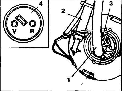
Rice. 255 Disconnecting hoses
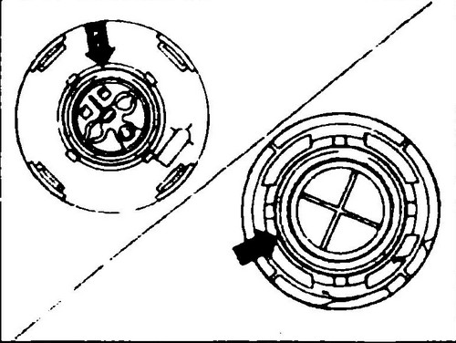
Rice. 256 Fitting O-rings
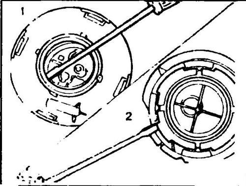
Rice. 257 Removing the circlip and bayonet ring
♦ Disconnect the bayonet connector at the top of the fuel pump/fuel level sensor unit by turning to the left.
♦ Remove the fuel level sensor from the bottom of the assembly housing.
Disconnect the fuel supply hose (1, see Fig. 255), the fuel return hose (2) and the fuel pump connector (3). ♦ Use a screwdriver to remove the upper circlip (1, see fig. 257) and the bayonet ring (2) (on the bottom of the housing).
♦ Open the upper part of the housing with a screwdriver (see the arrow in fig. 258) and remove it from the lower part.
Rice. 258 Removing the top part of the pump/sensor assembly
♦ Remove the fuel pump from the bottom of the assembly housing.
Installing
♦ Install the fuel pump O-rings (see arrow fig. 256) at the top and bottom of the housing from above and below.
♦ Secure the top O-ring with the circlip and the bottom O-ring with the bayonet ring.
♦ When assembling, coat the top housing ring with grease.
♦ Fit the fuel supply and return hoses and secure with clamps.
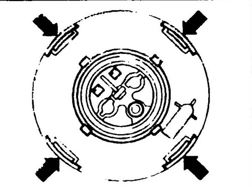
When doing so, observe the marking (4) on the cover tubes (3, Fig. 255). ♦ Install the pump/sensor assembly into the fuel tank, turn it from left to right to lock the bayonet connector.
♦ Lubricate and install the O-ring (5) of the cover (2) (see fig. 253).
♦ Install the cap so that the marking on the cap matches the marking on the fuel tank (see fig. 254).
♦ Fit and tighten the union nut.
♦ Fit the fuel supply and return hoses and secure with clamps.
♦ Connect the wiring connector.
♦ Replace the sensor guard.
♦ Reinstall the floor covering, secure the edges with tape.
♦ Connect the terminals to the battery.
The principle of operation of the Digifant system . Checking the fuel pump Conveyor .