Digifant Fuel Injection - 2.0L Engine
Digifant engine management system from Bosch. On fig. 263 shows the placement of system nodes in the engine compartment. In this system, fuel delivery and ignition timing are controlled by a single electronic microprocessor module. The device receives information about the current engine load and, based on it, the amount of fuel supplied to the combustion chamber, the injection moment, and the optimal ignition timing are calculated. The microprocessor module that controls the Transporter T4 is equipped with a fault recording unit. If any sensor or other monitored unit is damaged or out of order, information about the malfunction will be recorded in the memory block, from where the information can then be read. Such self-diagnosis of the system can only be performed using special equipment from VW. After the fault has been eliminated, the contents of the fault memory are reset to zero.

Rice.
263 Digilant injection system components 1 - air filter, 2 - intake duct, 3 - lambda probe connector, 4 - throttle body, 5 - throttle position sensor, 6 - injector, 7 - fuel distributor, 9 - fuel pressure regulator , 9 - intake manifold, 10 - frequency stabilization valve XX, 11 - pipe plug for measuring CO content in exhaust gases, 12 - vacuum hose, 13 - microprocessor module, 14 - ignition coil, 15 - cold start valve, 16 - ignition distributor, 17 - fan thermal switch with sensor for coolant temperature indicator, 18 - coolant temperature sensor, 19 - crankcase ventilation system pressure control valve, 20 - frequency adjustment screw XX, 21 - CO content adjustment potentiometer in exhaust gases
In the classic Digifant system, the fuel request signal depends on the amount of incoming air.
It is transmitted to the microprocessor module as an electronic signal from the air mass meter. In VW T4 cars, the system has a simplified design - there is no air flow meter. The microprocessor module sends signals to the injectors as well as the ignition coil to change the ignition timing. This ensures the optimum point at which fuel injection and ignition take place.
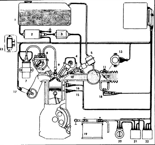
Rice.
265 Digifant System Diagram - Classic 1 - fuel tank, 2 - electric fuel pump, 3 - fuel filter, 4 - fuel distributor, 5 - fuel pressure regulator, 6 - microprocessor module, 7 - ignition coil, 8 - ignition distributor with Hall sensor , 9 - spark plug, 10 - injector, 11 - frequency adjustment screw XX, 12 - throttle valve, 13 - throttle position sensor, 15 - engine temperature sensor, 16 - knock sensor, 17 - lambda probe, 18 - speed controller XX , 19 - battery, 20 - ignition switch, 21 - fuel pump relay, 22 - main relay, 23 - power module
The degree of atmospheric pollution is significantly reduced thanks to the use of a lambda probe, which provides constant monitoring of the ratio of the amount of fuel supplied to the incoming air.
Fuel pump device . Replacing the fuel filter Volkswagen Transporte r.