Engine management system
During start-up During
start-up, that is, during the time that the starter is on, the microprocessor module, after receiving information about the engine temperature, turns on power to the fuel pump of the Transporter T4 vehicle after a short period of time . Then, when the engine is already running, the microprocessor module, which receives signals about the crankshaft speed and its position, controls both injection and ignition.
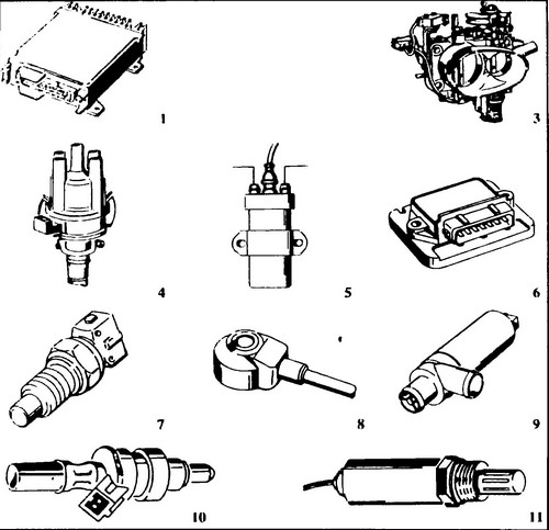
Rice.
265 The main components of the system 1 - microprocessor module, 3 - damper housing, 4 - ignition distributor with Hall sensor, 5 - ignition coil, 6 - power module, 7 - engine temperature sensor, 8 - knock sensor, 9 - frequency control XX, 10 - nozzle, 11 - lambda probe
After the engine warms up, the microprocessor module causes an increase in the amount of fuel, depending on the temperature of the coolant.
During engine start, the ignition timing is 10º until the end of start. The microprocessor module then adjusts the ignition timing.
Under normal operating conditions
After reaching the operating temperature of the engine, the microprocessor module, taking into account the data in the memory, sets the phases of operation, injection time and ignition timing, depending on the parameters (temperature, pressure) of the air in the manifold and the crankshaft speed.
The start of injection for each cylinder is set depending on the crankshaft speed.
Full Load
An engine operating at full load requires a properly rich mixture to produce maximum torque.
At this time, the microprocessor module, having processed the information received from the sensors for the position of the damper, speed and the division sensor in the intake manifold, transmits a signal to the injectors to increase the injection duration. In emergency situations
The microprocessor module ensures the correct operation of the system in emergency situations.
In the event of damage to one of the sensors, the microprocessor module automatically adapts to work in emergency conditions, so that the engine can work until the necessary repairs are made.
Only in the event of a failure of the Hall sensor, the engine will be stopped, since the microprocessor module will no longer receive a signal informing about the value of the crankshaft speed.
The main components of the system
Fuel pressure regulator
The fuel pressure regulator is installed at the end of the fuel line and regulates the pressure in the system. The pressure regulator consists of a metal housing (see Fig. 266), divided into two chambers by a diaphragm (4), pressed by a spring (5). If the fuel pressure exceeds the set value, the valve (7) opens and allows fuel to return to the tank.
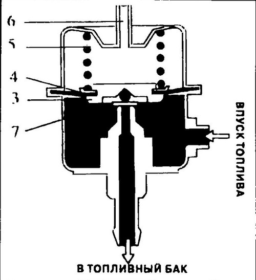
Rice. 266 Fuel pressure regulator device
A fitting (6) connects the engine intake manifold to the vacuum chamber (vacuum signal). This ensures that the pressure in the fuel system and the absolute pressure in the intake manifold are interdependent, regardless of operating conditions.
Idle speed controller
The XX frequency regulator is located in the bypass between the intake manifold and the flapper (instead of the secondary air valve in other injection systems). The regulator, by changing the cross section of the hole, regulates the frequency of the XX motor (see Fig. 267).
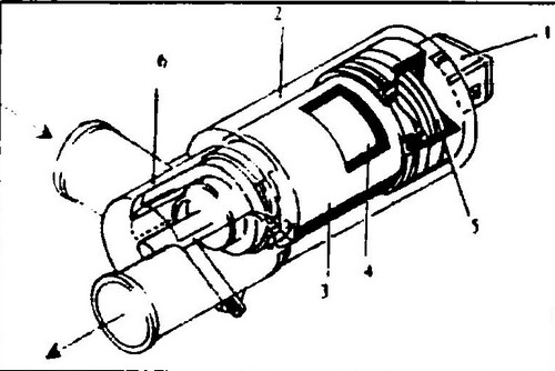
Rice.
267 Idle speed control device 1 - connector, 2 - housing, 3 - permanent magnet, 4 - armature, 5 - spring, 6 - slider
The microprocessor module is responsible for the operation of the frequency controller XX and sends it pulses that determine the cross section of the hole that supplies air to the motor.
Frequency constancy control XX
In all phases of operation, the single-turn regulator is responsible for the frequency XX.
At the lowest value of frequency XX, the regulator, acting on the bypass channel of the damper, increases the real frequency XX to the nominal value.
In addition to checking the XX frequency, the regulator also performs the functions of an additional air accumulator and ensures the operation of the air conditioner and power steering.
The XX frequency, except for the regulator, can be quickly changed by adjusting the ignition timing.
When the air conditioner is turned on, the microprocessor module increases the frequency to 1000 rpm.
After turning on the compressor, the microprocessor module maintains the frequency at a constant level by sending appropriate signals to the regulator.
This ensures the operation of the air conditioner and, if possible, a constant frequency XX of the engine.
Possible malfunctions caused by incorrect operation of the frequency controller XX.
- The engine does not start or starts with difficulty.
- Unstable idle speed.
- Increased fuel consumption.
Engine temperature sensor
The temperature sensor is a thermistor with a negative temperature coefficient of resistance, placed in a metal case (see Fig. 268). Being a semiconductor element, it reduces its resistance with increasing temperature (see Fig. 269).
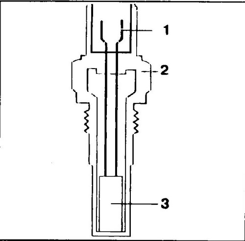
Rice.
268 Temperature sensor device 1 - electrical connector, 2 - case, 3 - thermistor
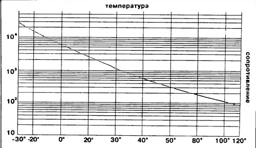
Rice. 269 Graph of change in the resistance of the engine temperature sensor
The sensor transmits information about changes in engine temperature to the microprocessor module.
This information is necessary to adjust the composition (enrichment) of the mixture until the engine reaches operating temperature.
The temperature sensor is located in the cylinder block, where, upon contact with the coolant, it receives its temperature.
Possible malfunctions caused by incorrect operation of the engine temperature sensor:
- The engine does not start or starts with difficulty.
- The engine stalls immediately after starting.
- Increased fuel consumption.
- Increased concentration of CO in the exhaust gases at idle.
Replacing the fuel filter T4 . Description of Digifant injection .