Sliding side door - removal, installation and adjustment
Removal
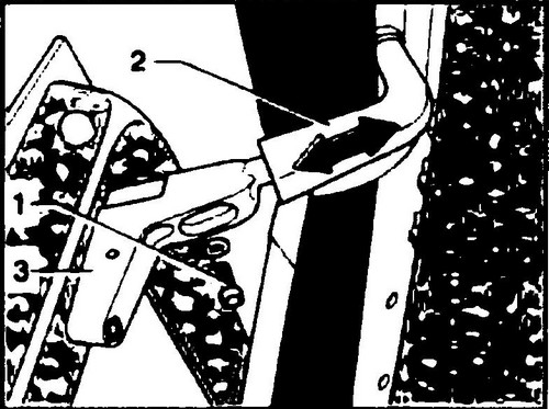
♦ Loosen the screw (1, see Fig. 488) and remove the stop (2) from the side guide on the outside of the body.
♦ On the inside of the door, unscrew the screw (5, Fig. 487) and remove the central stop (6).
Rice.
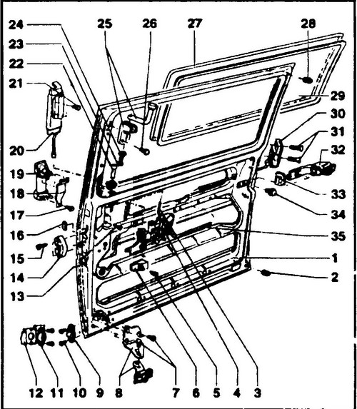
487 Sliding door device 1 - door, 2, 28 - rubber buffer, 3 - hand lock button rod, 4 - lock mechanism, 5, 7, 10, 15, 17, 31 - screws, 20 Nm, 6 - center stop , 8 - lower door guide with rollers, 9 - lower latch, 11 - lower latch catcher, 12 - body pillar, 13, 21, 23, 26 - bolts, 10 Nm, 14 - limiter, 16 - frame, 18 - mounting bracket handles, 19 - outer door handle, 20 - drive for unlocking the door from the inside, 22 - button, 24 - washer, 25 - top guide, 27 - glass frame, 29 - glass, 30 - central locking electromagnet, 32 - side slider, 33 - plug, 34 - bolt, 55 Nm, 35 - rod
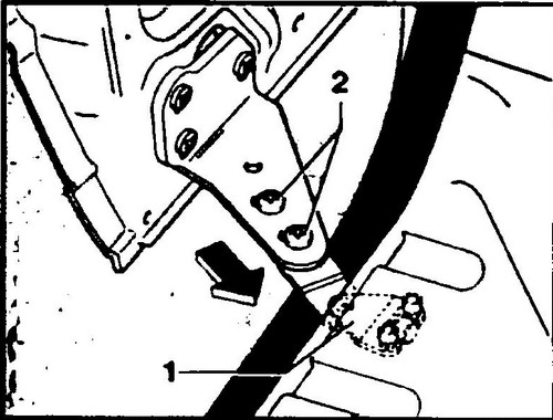
♦ Loosen the two screws (1, see Fig. 489) on the step and remove the lower door stop (2).
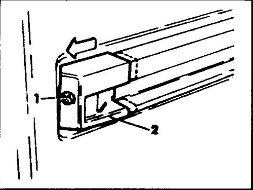
Rice. 488 Sliding door slide stop

Rice. 489 Bolts of fastening of the lower stop of a door
♦ Open the sliding door as far as it will go and move the lower guide away from the Transporter T4 (see arrow in Fig. 490).
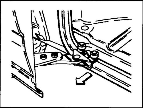
Rice. 490 Detaching the lower door rail
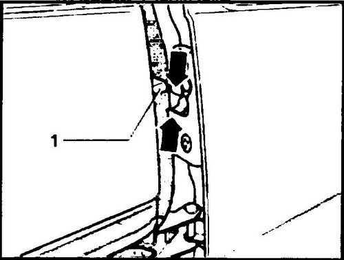
♦ Carefully, keeping the door hanging, remove the upper door guide from the body groove (see Fig. 491).
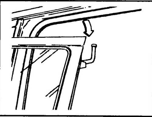
Rice. 491 Detaching the upper door guide
♦ After removing it from the opening, move the door back so that the side slide (32, Fig. 487) comes out of the outer side guide.
Once removed, set the door aside. Installation
Installation is carried out in the reverse order.
For screw tightening torques, see fig. 487. Adjustment
♦ Before adjustment, remove the decorative panel of the door.
Adjusting the position of the door (side slider, upper, lower guides, clamps)
The principle of adjustment is the same in all cases: loosen the corresponding fasteners, align the door, tighten the fasteners.
When adjusting the slider position:
♦ Loosen the screws securing the lock bracket to the body pillar.
♦ Close the sliding door and loosen the bolts (34, Fig. 487) on the interior side.
♦ Lift the door with a helper and move the slide with the bolts as far forward as possible.
♦ Bolts (34) tighten to 60 Nm.
Sliding door guide adjustment
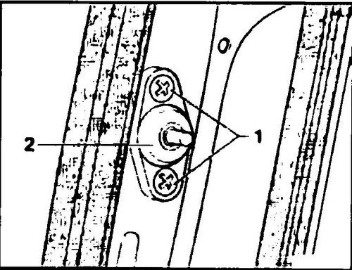
♦ Loosen the bolt (1, fig. 492) - top guide or (2, fig. 493) - bottom guide, adjust as described above, tighten screws to 20 Nm.
Rice. 492 Upper door guide
Rice. 493 Lower door guide
Adjustment of the lock bracket
Produced in the same way as described above.
After adjustment, tighten the bracket fastening screws with a torque of 20 Nm. The bracket must be located along the axis of the door lock groove (see Fig. 494). In the closed position, the door should sit tightly in the opening.
Rice. 494 Adjusting the position of the lock shackle
Adjustment of door clamps
Clamps (see Fig. 495) serve to prevent vibration of the side door in the opening. The adjustment is made in the same way as described above. Tighten the fixing screws to 20 Nm.
Rice. 495 Door lock