Suspension upper ball joint replacement
The upper control arms can only be removed after the front suspension beam has been removed. Replacing the upper hinges is quite simple. On fig. 383 shows the attachment of the ball joint to the upper wishbone and steering knuckle of the Transporter T4 . The eccentric (12) serves to adjust the angle of the wheel.
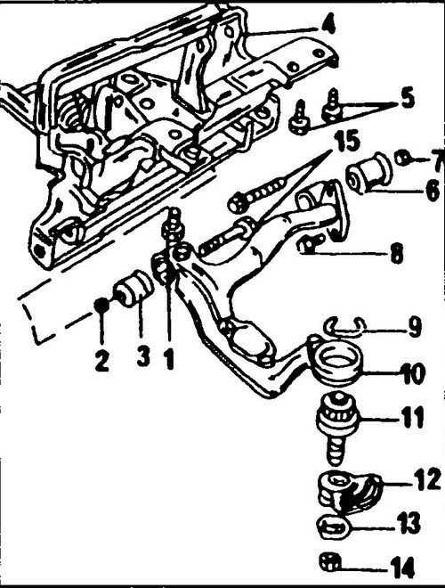
Rice.
383 The device of the upper transverse arm and upper ball joint 1 - bolt, 160 Nm, 2, 14 - nut, 110 Nm, 3 - front silent block. 4 - front suspension beam, 5 - bolt, 100 Nm, 6 - rear silent block, 7 - nut, 100 Nm, 8 - bolt, 9 - ball joint retaining spring, 10 - upper transverse arm, 11 - upper ball joint , 12 - adjusting eccentric, 13 - eccentric washer, 15 - bolt securing the transverse arm to the front suspension beam

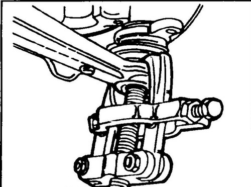
Rice. 384 Fastening the lower transverse arm to the steering knuckle. The arrow shows one of the two bolts.
The eccentric is blocked by a bolt screwed into the steering knuckle. An eccentric washer is placed at the bottom of the ball joint. Various universal pullers can be used to remove the ball joint. The designs of several of them are shown in Fig. 385 and 386.
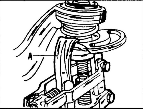
Rice. 385 Removing the adjusting eccentric from the ball joint pin
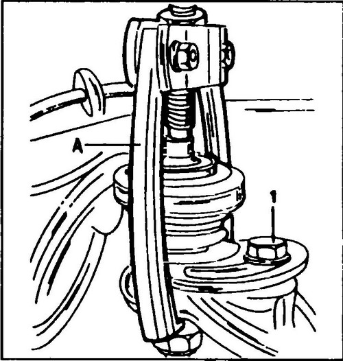
Rice. 386 Puller (a) used to remove and install the upper ball joint Locking bolt (1) tighten to 60Nm
The joint is replaced as follows:
♦ Fit the front suspension with load-bearing supports, or loosen the tension of the torsion bar by unscrewing the bolt (42) (see fig. 378).
♦ First loosen the drive axle bolt before lifting and jacking up the front of the vehicle.
♦ Remove the bolts securing the brake caliper.
Disconnect the caliper from the steering knuckle and hang it on a wire from the front suspension so that it does not hang on the brake hose. ♦ Remove both bolts (see fig. 384 - the second bolt is on the opposite side) and disconnect the ball joint together with the lower transverse arm from the steering knuckle.
♦ Mark the position of the eccentric (12) (see Fig. 383) in relation to the steering knuckle.
If you do not, then you will have to adjust the tilt of the wheel later. ♦ Remove the nut (14) securing the ball joint from below.
This nut is self-locking and must be replaced after each unscrewing. ♦ Mark the position of the eccentric washer (13) and then remove it.
♦ Remove the bolt blocking the eccentric on the steering knuckle.
♦ Disconnect the tie rod from the knuckle arm.
♦ Push up the upper transverse arm and disconnect the steering knuckle assembly.
The ball joint is replaced on the removed steering knuckle. ♦ Remove the adjusting eccentric using a puller (see fig. 385).
The figure shows a Kukku 204-2 puller (A). The paws of the puller must be brought behind the eccentric. ♦ From the hole of the transverse arm intended for the ball joint, remove the circlip upwards.
In this case, you can use a screwdriver. ♦ The puller shown in fig.
386, remove the ball joint from the steering knuckle. The puller shown in the figure (A) is a universal one. On fig.
386 also shows the bolt (1) used to block the adjusting eccentric. ♦ Use a puller (see fig. 386) to install a new ball joint in the transverse arm.
After the hinge is fully installed, install the snap ring into the groove of the mounting hole. ♦ Install the adjusting eccentric on the hinge with a puller.
♦ Install the front suspension knuckle and connect the upper ball joint to it.
The ball stud shaft must not be lubricated. The position of the adjusting eccentric during installation does not play any role. ♦ Loosen the nut and knock out the lower bolt from the shock absorber mounting ring.
If necessary, remove the air guide sheet. On the other hand, disconnect the stabilizer mount. ♦ Install the eccentric washer so that the previously marked marks coincide and tighten the ball stud nut with your fingers.
♦ Set the adjusting eccentric (12, fig. 383) according to the marks made during removal, tighten the bolt (1, fig. 386) to 60 Nm.
♦ Tighten the ball stud nut to 110 Nm. Each time a new nut must be used. If the ball pin rotates during the tightening of the nut, then in this case it is necessary to tighten the joint with a puller, as shown in fig. 387.
Rice. 387 Disconnecting the lower ball joint for dismantling the lower transverse arm
♦ Set the lower control arm pivot in the steering knuckle and tighten both mounting bolts.
♦ Install the stabilizer mounting support in the appropriate position.
Insert the long bolt through the connector into the transverse arm. Install a sheet that directs the passing air (if any) and, on the other hand, put a shock absorber on the bolt; Tighten the nut to a torque of 160 Nm. ♦ Reinstall the brake caliper.
Tighten the fastening bolts to a torque of 160 Nm. ♦ Rest the tie rod end in the knuckle arm.
Tighten the new self-locking nut to 40 Nm. ♦ Remove the unloading supports.