Diesel engine pistons and connecting rods
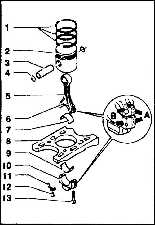
On fig. 213 shows the arrangement of the piston-rod assembly. It is similar to the corresponding unit in the T4 gasoline engine , with the only difference that the pistons of diesel engines have selections in the bottoms.
Rice.
213 Piston-connecting rod arrangement 1 - piston ring, 2 - piston, 3 - piston pin, 4 - circlip, 5 - connecting rod, 6 - dowel pin, 7, 9 - bearing shell, 8 - cylinder block, 10 - cap connecting rod, 11 - oil jet, 12, 13 - bolts
To remove the pistons and connecting rods, the engine must be dismantled from the Volkswagen Transporter T4 , and then the cylinder head must be removed.
On fig. 214 shows the numbering of pistons in a five-cylinder engine.
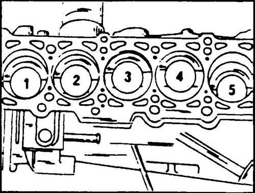
Rice. 214 Marking the pistons of a five-cylinder engine before dismantling
In diesel engines, the correct installation of the pistons can also be checked by samples on the skirt for the oil nozzle, which should be located on the side of the block nozzles.
In the skirts of the pistons of both diesel engines, recesses are made for nozzles that inject oil to cool the pistons. In the BDC position, the selection ensures that the pistons do not collide with the above nozzles. During assembly, these cutouts must be properly oriented (Fig. 215).
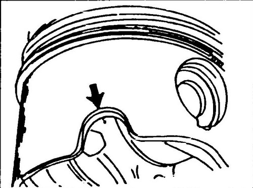
Rice. 215 Piston cutout
Pistons and connecting rods of diesel engines are checked in the same way as pistons and connecting rods of gasoline engines.
The dimensions required for this are given in table 1. Before measuring the piston ring lock gaps, unscrew the piston cooling nozzles, otherwise it will not be possible to install the piston rings in the cylinders . On fig. 216 shows the placement of these injectors in the engine block. The radial clearance of the connecting rod bearings is measured using Plastigage plastic wires.
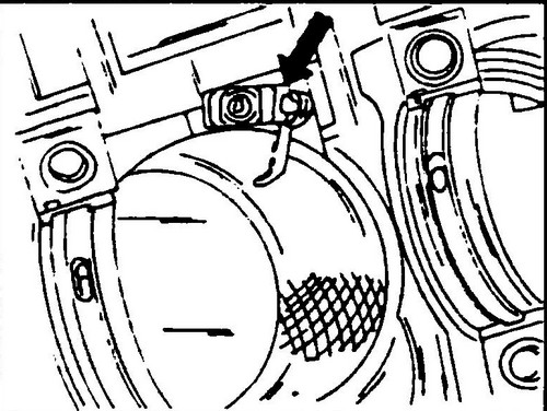
Rice. 216 The position of the nozzles supplying oil to cool the pistons in the engine block
The assembly of the piston with the connecting rod, as well as the installation of the assembly in the engine, is carried out in the same way as in a gasoline engine.
♦ If the piston oil nozzles have been removed, they must be reinstalled and the fixing bolts tightened to 10 Nm.
Lubricate the cylinder bores liberally with clean engine oil. The tides on the lower head of the connecting rod, as well as the cover of the lower head of the connecting rod, must be on the same side and must be directed towards the crankshaft belt pulley (see Fig. 213). The arrows on the bottoms of the pistons must point towards the front of the engine.
♦ Rotate the piston ring locks evenly in a circle (every 120º).
On fig. 213 shows the recommended orientation of piston ring locks relative to the piston pin. ♦ Place a piston ring crimp on the piston and push the rings into the piston grooves.
Check if the rings are fully seated in the grooves. If you do not have this ring compression tool, you can use a wide hose clamp or even a thin metal strip (tin) that is wound around the rings and compressed at the ends so that the rings fit completely into the grooves. At worst, two old half-liners will help - they allow you to press the piston rings in four places around the perimeter at once. Before inserting the piston into the cylinder, be sure to check whether both circlips of the piston pin are installed, since the first circlip is installed first, then the piston pin itself is installed, and only then the second ring is installed. ♦ It is also necessary to check whether the dowel pins are on the bottom end of the connecting rod.
They must be firmly seated and in no case can they be in the cap of the lower head of the connecting rod. ♦ Lay the engine on its side.
This will protect against possible damage to the cylinder surface. Before inserting the connecting rod into the cylinder, install a semi-liner into the hole in the lower head of the connecting rod. The protrusion of the half-liner should be in the recess at the edge of the hole. Rotate the crankshaft so that the two connecting rod journals are at BDC. ♦ Insert the connecting rod into the cylinder from above.
For greater safety, you can wrap the lower head of the connecting rod with tape (adhesive tape). ♦ Insert the piston gradually into the cylinder so that all the piston rings are in the cylinder and the lower head rests on the crankpin.
♦ Place the second bearing half into the connecting rod cap and lubricate it with clean engine oil.
Place the cover on the bottom head of the connecting rod, and then lightly tap it to “sit down” in place. The dowel pins must fit into the holes in the connecting rod cap. Be sure to check whether there are tides on the lower connecting rod head and its cover on one side. ♦ Lubricate the threads and bearing surface of the head of the new connecting rod bolt with engine oil.
♦ Tighten the connecting rod bolts evenly and in turn to a torque of 30 Nm.
From this position, tighten the bolts an additional quarter turn (90º) so that the bolts receive their initial tension. ♦ After installing the connecting rods on the crankpins, turn the crankshaft several times to immediately detect any obstruction to free rotation.
♦ Check once again the designation of all connecting rods and the correct installation of the pistons.
Make sure the recesses in the pistons for the oil injectors are on the correct side. ♦ Use a feeler gauge to check the clearance between the side surface of the connecting rod and the bearing surface of the crankshaft. This is the axial clearance of the connecting rod bearing. It should not exceed 0.40 mm in a five-cylinder engine and 0.37 mm in a four-cylinder engine.
Instructions: how to open doors from the inside . Volkswagen ignition lock design .