3 Replacing the rear trailing arm
The rear trailing arm mount is designed so that the Transporter T4 rear wheel toe can be adjusted.
Before removing the trailing arm it is necessary to mark the position of the bolt (15, fig. 400), otherwise the rear suspension geometry will need to be measured and adjusted after installation.
When removing the trailing arm, use fig. 400. ♦ Remove the coil spring as described above, with the only difference being that this time the lower shock mount must be removed.
Dismantling the shock absorber is described above. Then, if necessary, you can remove the shock absorber. Mark the position of the head of the bolt (15) in relation to the lever bracket in the body. ♦ Loosen nuts (16) and (18).
♦ If a stabilizer is installed, remove it by detaching it from the body and also from the lever on the underside.
♦ Loosen the mounting bolt and disconnect the handbrake link bracket (25).
♦ Disconnect the rear brake pressure regulator spring from the lever.
If the trailing arm is replaced, the rear brake pressure regulator must be adjusted. ♦ If an ABS system is installed, loosen the bolts securing the wheel sensor (31) and remove this sensor from the arm.
Wrap the end of the sensor with tape to protect it from damage and dirt. ♦ Remove the brake drum as described in chapter 9 and then the brake shield (5) (fig. 406). The parking brake link does not need to be disconnected, but the brake hose must be disconnected.
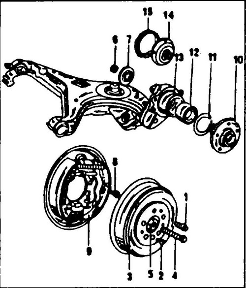
Rice.
406 Wheel hub assembly 1 - wheel bolt 160 Nm, 2, 8 - top bolts, 3 - brake drum, 4 - bolt, 5 - washer, 6 - self-locking nut, 200 Nm, 7 - disc 9 - shield brakes, 10 - wheel hub,
11 - retaining spring ring, 12 - wheel bearing, 13 - trailing arm, 14 - pressure plate (in vehicles with ABS), 15 - speed sensor prong (for ABS system)
♦ Knock out the bolts securing the arm to the body bracket from both silent blocks and remove the trailing arm.
To replace the silent blocks of the lever, special tools are required. ♦ Install the lever in reverse order.
The shock absorber installation method is described above. Tighten both bolts and nuts of the silent blocks of the lever by hand. Finally, the nuts are tightened only after the car is put on wheels. ♦ Turn the head of the bolt (15) (see fig. 400) in the rear arm support so that the mark made before removal is in line with the mark on the arm bracket.
♦ While holding the bolt (15), tighten the nut to 100 Nm, after tightening check that both marks made with a core match.
♦ If the marks do not line up, loosen the nut (16) again and correct the position.
♦ Hold the head of the bolt (17) and tighten the nut (18) to 160 Nm.
♦ Loosen the bolts securing the stabilizer mounts with a torque of 30 Nm.
If the trailing arm has been replaced, the rear brake pressure regulator must be adjusted. If the lever has not been replaced, secure both governor springs to the double-ended governor lever.